VEHICLE STABILITY CONTROL SYSTEM, Diagnostic DTC:C1379
| DTC Code | DTC Name |
|---|---|
| C1379 | Downhill Assist Control Switch Malfunction (Test Mode DTC) |
DESCRIPTION
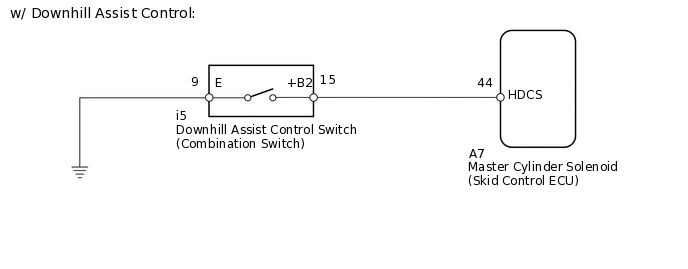
w/ Downhill Assist Control:
DTC C1379 is cleared when the downhill assist control switch sends a downhill assist control operation signal or when test mode ends.
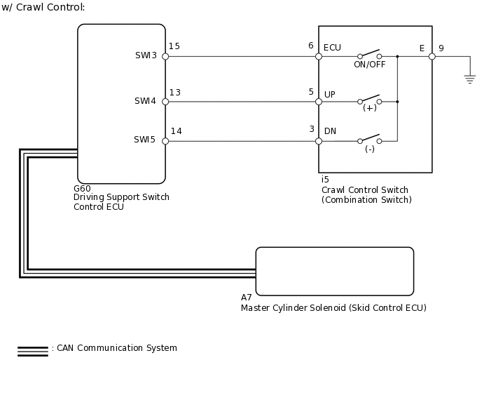
w/ Crawl Control:
DTC C1379 is cleared when the crawl control switch sends a crawl control operation signal or when test mode ends.
DTC No. |
Detection Item |
DTC Detection Condition |
Trouble Area |
|---|---|---|---|
C1379 |
Downhill Assist Control Switch Malfunction (Test Mode DTC) |
Stored only during test mode. |
|
WIRING DIAGRAM
CAUTION / NOTICE / HINT
When replacing the master cylinder solenoid, perform calibration (Click here).
PROCEDURE
CONFIRM VEHICLE SPECIFICATIONS
Confirm the vehicle specifications.
Result
Result
Proceed to
w/ Downhill Assist Control
A
w/ Crawl Control
B
B CHECK CAN BUSClick here
READ VALUE USING INTELLIGENT TESTER (DOWNHILL ASSIST CONTROL SW)
Turn the engine switch off.
Connect the intelligent tester to the DLC3.
Turn the engine switch on (IG).
Turn the intelligent tester on.
Enter the following menus: Chassis / ABS/VSC/TRC / Data List.
Check the Data List for proper functioning of the downhill assist control switch.
Chassis > ABS/VSC/TRC > Data List
Tester Display
Measurement Item
Range
Normal Condition
Diagnostic Note
Downhill Assist Control SW
Downhill assist control switch
ON or OFF
ON: Downhill assist control on
OFF: Downhill assist control off
-
OK
The intelligent tester displays ON or OFF according to downhill assist control switch operation.
Result
Result
OK
NG
NG INSPECT DOWNHILL ASSIST CONTROL SWITCH (COMBINATION SWITCH)Click here
CHECK TEST MODE DTC
Perform the downhill assist control switch check in the Test Mode Procedure.
OK
Test mode DTC C1379 is cleared.
Result
Result
OK
NG
Chassis > ABS/VSC/TRC > Utility
Tester Display
Test Mode
INSPECT DOWNHILL ASSIST CONTROL SWITCH (COMBINATION SWITCH)
Remove the combination switch.
-
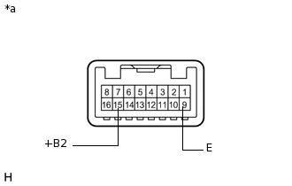
*a
Component without harness connected
(Downhill Assist Control Switch [Combination Switch])
Measure the resistance according to the value(s) in the table below.
Standard Resistance
Tester Connection
Switch Condition
Specified Condition
15 (+B2) - 9 (E)
Pressed
Below 1 Ω
Not pressed
10 kΩ or higher
Result
Result
OK
NG
CHECK HARNESS AND CONNECTOR (SKID CONTROL ECU - DOWNHILL ASSIST CONTROL SWITCH)
Disconnect the A7 skid control ECU connector.
Disconnect the i5 combination switch connector.
Measure the resistance according to the value(s) in the table below.
Standard Resistance
Tester Connection
Condition
Specified Condition
A7-44 (HDCS) - i5-15 (+B2)
Always
Below 1 Ω
A7-44 (HDCS) - Body ground
Always
10 kΩ or higher
i5-9 (E) - Body ground
Always
Below 1 Ω
Result
Result
OK
NG
NG REPAIR OR REPLACE HARNESS OR CONNECTOR
CHECK CAN BUS
Check that there are no problems with the CAN communication system.
Result
Result
OK
NG
READ VALUE USING INTELLIGENT TESTER (CRAWL CONTROL SWITCH)
Turn the engine switch off.
Connect the intelligent tester to the DLC3.
Turn the engine switch on (IG).
Turn the intelligent tester on.
Enter the following menus: Body Electrical / D-SEAT SW / Data List.
Check the Data List for proper functioning of the crawl control switch.
Body Electrical > D-SEAT SW > Data List
Tester Display
Measurement Item
Range
Normal Condition
Diagnostic Note
Crawl Control Main Switch
Crawl control switch (ON/OFF switch)
ON or OFF
ON: Crawl control on
OFF: Crawl control off
-
Crawl Control Up Switch
Crawl Control Switch (Speed selector switch)
ON or OFF
ON: Speed selector switch pushed to the up side and held
OFF: Speed selector switch not pushed to the up side
-
Crawl Control Down Switch
Crawl Control Switch (Speed selector switch)
ON or OFF
ON: Speed selector switch pushed to the down side and held
OFF: Speed selector switch down side not pushed to the down side
-
OK
The intelligent tester displays according to crawl control switch operation.
Result
Result
OK
NG
NG CHECK HARNESS AND CONNECTOR (CRAWL CONTROL SWITCH - DRIVING SUPPORT SWITCH CONTROL ECU)Click here
CHECK TEST MODE DTC
Perform the crawl control switch check in the Test Mode Procedure.
OK
Test mode DTC C1379 is cleared.
Result
Result
OK
NG
Chassis > ABS/VSC/TRC > Utility
Tester Display
Test Mode
CHECK HARNESS AND CONNECTOR (CRAWL CONTROL SWITCH - DRIVING SUPPORT SWITCH CONTROL ECU)
Disconnect the i5 combination switch connector.
Disconnect the G60 driving support switch control ECU connector.
Measure the resistance according to the value(s) in the table below.
Standard Resistance
Tester Connection
Condition
Specified Condition
i5-6 (ECU) - G60-15 (SWI3)
Always
Below 1 Ω
i5-6 (ECU) - Body ground
Always
10 kΩ or higher
i5-5 (UP) - G60-13 (SWI4)
Always
Below 1 Ω
i5-5 (UP) - Body ground
Always
10 kΩ or higher
i5-3 (DN) - G60-14 (SWI5)
Always
Below 1 Ω
i5-3 (DN) - Body ground
Always
10 kΩ or higher
i5-9 (E) - Body ground
Always
Below 1 Ω
Result
Result
OK
NG
NG REPAIR OR REPLACE HARNESS OR CONNECTOR
INSPECT CRAWL CONTROL SWITCH (COMBINATION SWITCH)
Remove the combination switch.
-
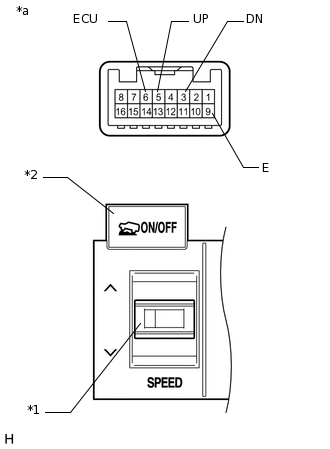
*1
Speed Selector Switch
*2
ON/OFF Switch
*a
Component without harness connected
(Crawl Control Switch [Combination Switch])
Measure the resistance according to the value(s) in the table below.
Standard Resistance
Tester Connection
Switch Condition
Specified Condition
5 (UP) - 9 (E)
SPEED (UP): Pressed
Below 1 Ω
SPEED (UP): Not Pressed
10 kΩ or higher
3 (DN) - 9 (E)
SPEED (DOWN): Pressed
Below 1 Ω
SPEED (DOWN): Not Pressed
10 kΩ or higher
6 (ECU) - 9 (E)
ON/OFF: Pressed
Below 1 Ω
ON/OFF: Not pressed
10 kΩ or higher
Result
Result
OK
NG