HEATER ASSEMBLY INSTALLATION
PROCEDURE
INSTALL HEATER AND ACCESSORY ASSEMBLY
-
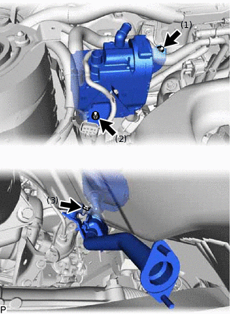
Install the heater and accessory assembly with the 3 nuts.
9.8 N*m
100 kgf*cm
87 in.*lbf
Tip:Tighten the nuts in the order shown in the illustration to install the heater and accessory assembly.
Engage the clamp.
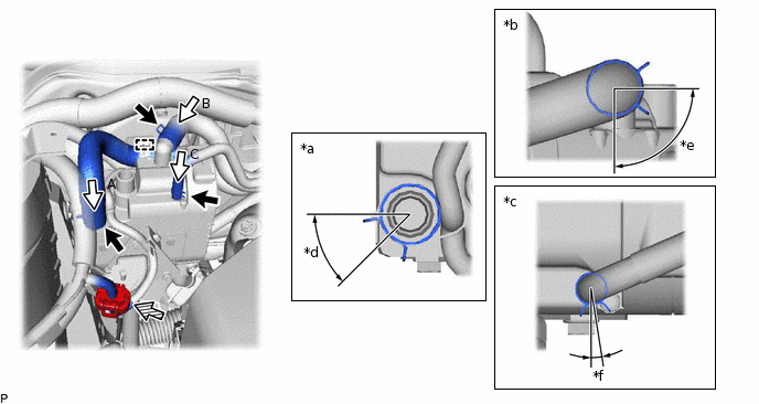
*a
View A
*b
View B
*c
View C
*d
Clip installation angle (30°20' to 60°20')
*e
Clip installation angle (75° to 105°)
*f
Clip installation angle (-6°19' to 24°19')
Connect each hose and engage the 3 clips within the area shown in the illustration.
Connect the connector.
-
INSTALL NO. 2 HEAT EXCHANGER UNIT GASKET
Install a new No. 2 heat exchanger unit gasket.
INSTALL NO. 1 EXHAUST PIPE SUB-ASSEMBLY
Install the No. 1 exhaust pipe sub-assembly with the 3 nuts.
9.8 N*m
100 kgf*cm
87 in.*lbf
Tip:Make sure to install the pipe from the vehicle front.
INSTALL AIR DUCT
Install the air duct with the clip.
INSTALL FRONT FLOOR COVER RH
Engage the 3 clips.
Install the front floor cover RH with the bolt and clip.
INSTALL OUTER COWL TOP PANEL
INSTALL DIFFERENTIAL PRESSURE SENSOR ASSEMBLY (for 1AD-FTV)
INSTALL NO. 2 HEATER AIR DUCT SPLASH SHIELD SEAL
INSTALL WATER GUARD PLATE LH
INSTALL WINDSHIELD WIPER MOTOR AND LINK ASSEMBLY