CYLINDER BLOCK DISASSEMBLY
PROCEDURE
REMOVE PISTON SUB-ASSEMBLY WITH CONNECTING ROD
-
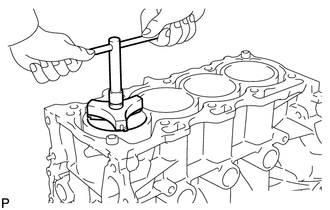
Using a ridge reamer, remove all the carbon from the top of the cylinder.
-
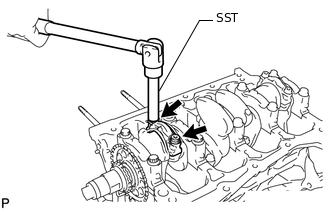
Using SST, uniformly loosen the 2 connecting rod bolts.
09205-16010
-
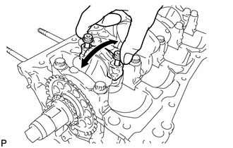
Using the 2 removed connecting rod bolts, remove the connecting rod cap and lower connecting rod bearing by wiggling the connecting rod cap back and forth.
Tip:Keep the lower connecting rod bearing inserted in the connecting rod cap.
Push the piston, connecting rod and upper connecting rod bearing through the top of the cylinder block sub-assembly.
Note:Do not disassemble the piston, piston pin and connecting rod. If the piston pin is removed, the piston, piston pin and connecting rod cannot be reused.
Tip:Keep each connecting rod bearing, connecting rod and connecting rod cap as a set.
Arrange the removed parts in the correct order.
-
REMOVE CONNECTING ROD BEARING
Remove the connecting rod bearings from the connecting rod cap and connecting rod.
Tip:Arrange the removed parts in the correct order.
REMOVE PISTON RING SET
-
Using a piston ring expander, remove the No. 1 ring and No. 2 ring.
Remove the oil ring and oil ring expander by hand.
Tip:Arrange the removed parts in the correct order.
-
REMOVE CRANKSHAFT
-
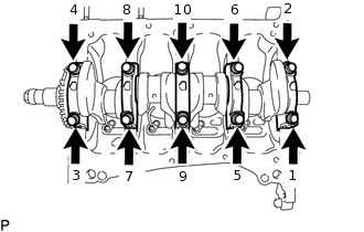
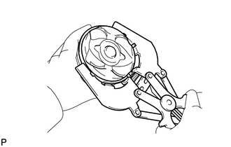
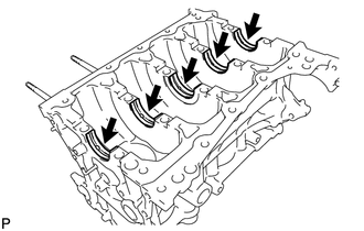
Uniformly loosen and remove the 10 crankshaft bearing cap set bolts in the order shown in the illustration.
-
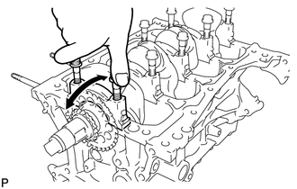
Using the 2 removed crankshaft bearing cap set bolts, remove the 5 crankshaft bearing caps and 5 lower crankshaft bearings.
Note:Insert the crankshaft bearing cap set bolts into the crankshaft bearing caps in turn. Ease the crankshaft bearing cap out by gently pulling it up while wiggling it back and forth, as shown in the illustration. Be careful not to damage the contact surfaces of the crankshaft bearing cap and cylinder block sub-assembly.
Tip:Keep each lower crankshaft bearing and crankshaft bearing cap as a set.
Arrange the crankshaft bearing caps in the correct order.
-
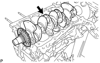
Remove the crankshaft.
-
REMOVE UPPER CRANKSHAFT THRUST WASHER
-
Remove the 2 upper crankshaft thrust washers from the cylinder block sub-assembly.
-
REMOVE CRANKSHAFT BEARING
-
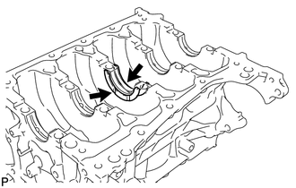
Remove the 5 upper crankshaft bearings from the cylinder block sub-assembly.
Tip:Arrange the removed parts in the correct order.
-
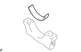
Remove the 5 lower crankshaft bearings from the 5 crankshaft bearing caps.
Tip:Arrange the removed parts in the correct order.
-
REMOVE OIL CHECK VALVE SUB-ASSEMBLY
-
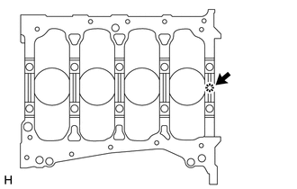
Using a magnet hand, remove the oil check valve sub-assembly from the cylinder block sub-assembly.
-
REMOVE NO. 1 OIL NOZZLE SUB-ASSEMBLY
-
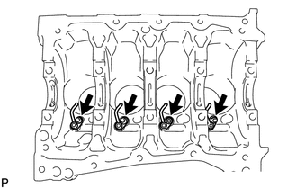
Using a 5 mm socket hexagon wrench, remove the 4 bolts and 4 No.1 oil nozzle sub-assemblies.
-
REMOVE OIL JET
-
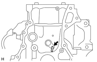
Remove the oil jet from the cylinder block sub-assembly.
-
CLEAN CYLINDER BLOCK SUB-ASSEMBLY
Note:If the cylinder is washed at high temperature, the cylinder liner will stick out beyond the cylinder block sub-assembly. Always wash the cylinder block sub-assembly at a temperature of 45°C (113°F) or less.