PARKING ASSIST ECU REMOVAL
PROCEDURE
-
PRECAUTION
Note
After turning the power switch off, waiting time may be required before disconnecting the cable from the negative (-) auxiliary battery terminal. Therefore, make sure to read the disconnecting the cable from the negative (-) auxiliary battery terminal notices before proceeding with work Click here.
-
REMOVE DECK BOARD ASSEMBLY
-
REMOVE NO. 1 DECK BOARD
-
REMOVE NO. 2 DECK BOARD
-
REMOVE REAR DECK FLOOR BOX
-
REMOVE DECK FLOOR BOX RH
-
DISCONNECT CABLE FROM NEGATIVE AUXILIARY BATTERY TERMINAL
Note
When disconnecting the cable, some systems need to be initialized after the cable is reconnected Click here.
-
REMOVE NO. 2 INSTRUMENT PANEL UNDER COVER SUB-ASSEMBLY (for LHD)
-
REMOVE GLOVE COMPARTMENT DOOR ASSEMBLY (for LHD)
-
REMOVE LOWER INSTRUMENT PANEL FINISH PANEL ASSEMBLY (for RHD)
-
REMOVE ECU INTEGRATION BOX RH (for LHD)
-
REMOVE ECU INTEGRATION BOX RH (for RHD)
-
Disconnect each connector.
-
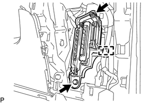
Disengage the clump.
-
Remove the bolt, nut and ECU integration box RH.
-
-
REMOVE PARKING ASSIST ECU
-
for LHD:
-
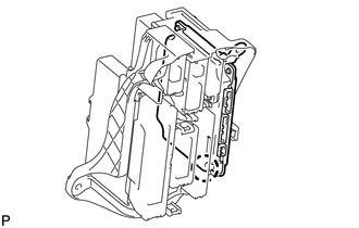
Disengage the claw and remove the parking assist ECU.
Tech Tips
When removing the parking assist ECU, if the bracket for the driving support ECU assembly is on top of the bracket for the parking assist ECU, remove the driving support ECU assembly first Click here.
-
-
for RHD:
-
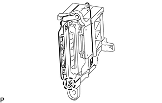
Disengage the claw and remove the parking assist ECU.
Tech Tips
When removing the parking assist ECU, if the bracket for the driving support ECU assembly is on top of the bracket for the parking assist ECU, remove the driving support ECU assembly first Click here.
-
-