ECD SYSTEM DETAILS
-
FUNCTION OF MAIN COMPONENTS
-
The main components of the engine control system are as follows:
Component Outline Quantity Function ECM Forest 2*1 1 The ECM effects overall control of the engine control system to suit the operating conditions of the engine in accordance with the signals provided by the sensors. 32-bit CPU*2 Injector Driver DC/DC Converter 1 The injector driver is used to drive the injector at high speeds. The injector driver has achieved high-speed driving under high fuel pressure conditions through the use of a DC/DC converter that provides a high voltage, quick-charging system. Turbo Pressure Sensor Semiconductor Silicon Chip Type 1 This sensor uses built-in semiconductors to detect the intake manifold pressure. Atmospheric Pressure Sensor Semiconductor Silicon Chip Type 1 This sensor, which is built into the ECM, uses semiconductors to detect the atmospheric pressure. Fuel Pressure Sensor Semiconductor Strain Gauge Type 1 This sensor uses built-in semiconductors to detect the internal pressure of the common-rail. Pressure Discharge Valve Solenoid Type 1 The pressure discharge valve regulates the fuel pressure. Crank Position Sensor Pick-up Coil Type
(Rotor Teeth/36-2)
1 This sensor detects the engine speed and performs the cylinder identification. Camshaft Position Sensor Pick-up Coil Type
(Rotor Teeth/5)
1 This sensor performs the cylinder identification. Intake Mass Air Flow Meter Sub-assembly*3 Hot-wire Type 1 This sensor uses a built-in hot-wire to directly detect the intake air mass. Intake Air Temperature Sensor
(Built into Intake Mass Air Flow Meter Sub-assembly)*4
Thermistor Type 1 This sensor detects the intake air temperature by means of an internal thermistor. Intake Air Temperature Sensor
(Air Cleaner Outlet)*5
Intake Air Temperature Sensor
(Intercooler Outlet)*6
Thermistor Type 1 This sensor detects the intake air temperature past the intercooler. Engine Coolant Temperature Sensor Thermistor Type 1 This sensor detects the engine coolant temperature by means of an internal thermistor. Fuel Temperature Sensor Thermistor Type 1 This sensor detects the fuel temperature in the supply pump by means of an internal thermistor. Throttle Position Sensor Non-contact Type 1 This sensor detects the diesel throttle valve opening angle. Accelerator Pedal Position Sensor Non-contact Type 1 This sensor detects the amount of pedal effort applied to the accelerator pedal. Nozzle Vane Position Sensor*7 Non-contact Type 1 This sensor detects the nozzle vane position. Suction Control Valve (SCV) Linear Solenoid Valve 1 The SCV position is controlled by the signals from the ECM, and a fuel volume that suits the SCV position is drawn into the pumping portion (plunger portion). Glow Plug Controller*1 Pulse Width Modulation (PWM) Driver 1 The glow plug controller controls the length of time for which the current is applied to the glow plug assemblies in accordance with the ECM signal. Injector Assembly 8-hole, Piezo Type*1 4 The injector injects the fuel to the combustion chamber in accordance with the ECM signals via the injector driver. 8-hole, Solenoid Type*8 6-hole, Solenoid Type*9
-
*1: Models compliant with EURO 5 emission regulations
-
*2: Except models compliant with EURO 5 emission regulations
-
*3: Models compliant with EURO 5, EURO 4 and EURO 2 emission regulations
-
*4: Models with intake mass air flow meter sub-assembly
-
*5: Models without intake mass air flow meter sub-assembly
-
*6: Models with intercooler
-
*7: Models with variable nozzle vane type turbocharger
-
*8: Models with variable nozzle vane type turbocharger (except models compliant with EURO 5 emission regulations)
-
*9: Models with wastegate valve type turbocharger
-
-
-
SYSTEM CONTROL
-
The engine control system has the following features. The ECM controls these systems:
System Outline Fuel Injection Volume Control Based on the signals received from the sensors, the ECM determines the fuel injection volume in accordance with the engine condition. Fuel Injection Timing Control Based on the signals received from the sensors, the ECM determines the fuel injection timing in accordance with the engine condition. During Starting Control To facilitate startability, the ECM optimally controls the injection volume and injection timing during starting. Idle Speed Control The ECM determines the idle speed in accordance with the engine condition, and controls the fuel injection volume in order to maintain the target idle speed. Fuel Pressure Control Based on the signals received from the sensors, the ECM controls fuel pressure using the Suction Control Valve (SCV) and pressure discharge valve in accordance with engine operating conditions. Pilot Injection Control Based on the signals received from the sensors, the ECM determines pilot injection volume/timing and interval (between pilot injection and main injection) in accordance with the engine condition. Glow Plug Control The ECM sends signals to the glow plug controller in accordance with engine conditions. Based on the signals, the glow plug controller controls the length of time for which the current is applied to the glow plug assemblies in each cylinder.*1 The ECM controls the length of time for which the current is applied to the glow plug assemblies, in accordance with the engine coolant temperature.*2 Diesel Throttle Control
-
Controls the diesel throttle valve opening angle in accordance with the engine condition.
-
Fully closes the diesel throttle valve in order to reduce the vibration when the engine is stopped.
Swirl Control*3 Based on the signals received from the sensors, the ECM controls the vacuum that is directed to the actuator via the VSV, in order to open and close the valve. Controls the valve opening in 2 stages: fully open and fully closed. Turbocharger Control*4 Based on the signals received from the sensors, the ECM controls the actuator in accordance with the engine condition. Air Conditioning Cut-off Control*5 By controlling the air conditioning compressor on or off in accordance with the engine condition, driveability is maintained. Engine Immobiliser*6 Prohibits fuel injection if an attempt is made to start the engine with an invalid ignition key. Oil Maintenance Management System*7 When the ECM determines engine oil and oil filter deterioration, the engine oil change reminder light turns on to inform the driver. Diagnosis When the ECM detects a malfunction, it diagnoses and memorizes the failed section. Fail-safe When the ECM detects a malfunction, it stops or controls the engine in accordance with the data already stored in the memory.
-
*1: Models compliant with EURO 5 emission regulations
-
*2: Except models compliant with EURO 5 emission regulations
-
*3: Models compliant with EURO 4 emission regulations and models compliant with EURO 2 emission regulations with variable nozzle vane type turbocharger
-
*4: Models with variable nozzle vane type turbocharger
-
*5: Models with air conditioning system
-
*6: Models with engine immobiliser system
-
*7: Models for Europe
-
-
-
FUNCTION
-
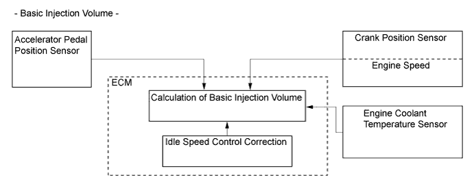
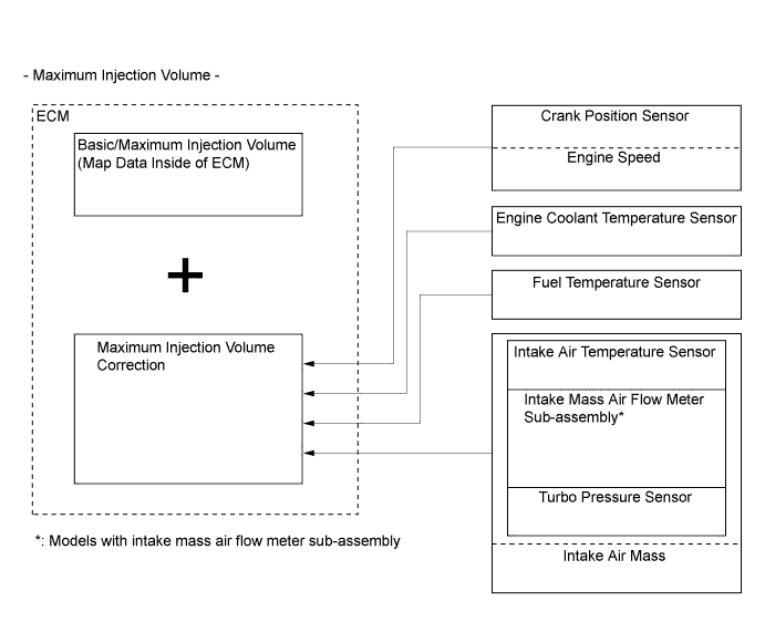
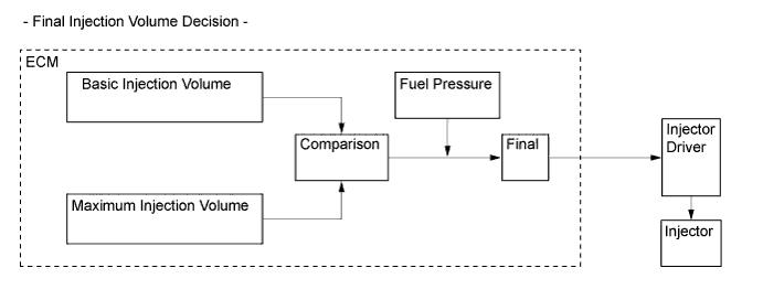
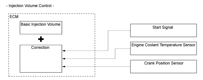
Fuel Injection Volume Control
-
The ECM calculates 2 types of values: the basic injection volume and the maximum injection volume. Then, the ECM compares the basic and maximum injection volumes, and determines the smaller calculated value to be the final injection volume.
-
-
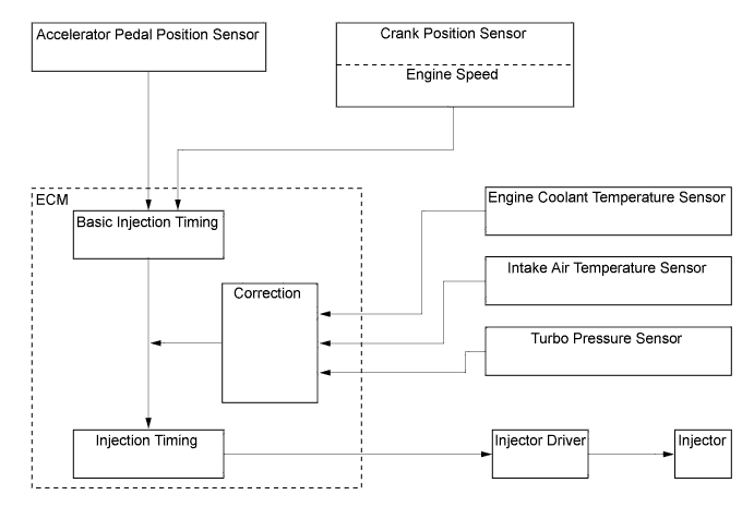
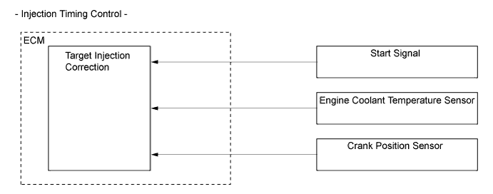
Fuel Injection Timing Control
-
Fuel injection timing is controlled as shown below:
-
-
During Starting Control
-
The starting injection volume is determined by adjusting the basic injection volume in accordance with the starter on signals (on time), engine coolant temperature sensor signals and engine speed signal. When the engine is cold, the engine coolant temperature will be lower and the injection volume will be greater.
-
To determine the starting injection timing, the target injection timing is corrected in accordance with the starter signals, engine coolant temperature, and engine speed. When the engine coolant temperature is low, if the engine speed is high, the injection timing is advanced.
-
-
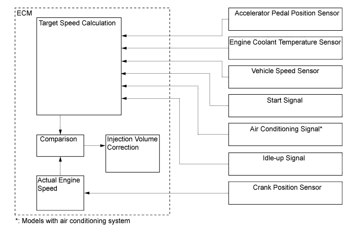
Idle Speed Control
-
Idle speed control correction is controlled as shown below:
-
-
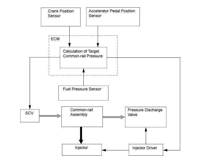
Fuel Pressure Control
-
The ECM calculates the target injection pressure (32 MPa to 200 MPa*1 or 32 MPa to 160 MPa*2) based on the signals from the accelerator pedal position sensor and the crank position sensor. To control fuel pressure, signals sent to the Suction Control Valve (SCV) of the supply pump assembly regulate the suction volume, and signals sent to the pressure discharge valve of the common-rail regulate the discharge volume, so that the pressure detected by the fuel pressure sensor matches the target injection pressure.
-
*1: Models compliant with EURO 5 emission regulations
-
*2: Except models compliant with EURO 5 emission regulations
-
-
-
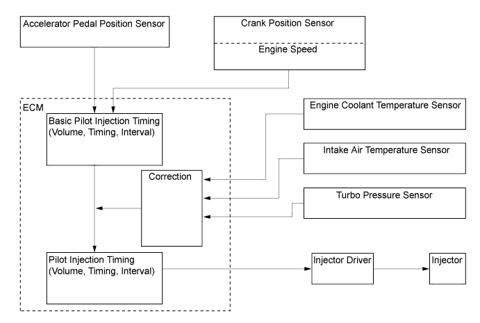
Pilot Injection Control
-
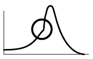
Pilot injection is a method that provides an auxiliary fuel injection before the main fuel injection takes place. The purpose of pilot injection is to gently start the combustion of the fuel of the main injection in order to reduce combustion noise.
State Pilot Injection Ordinary Injection Fuel Injection 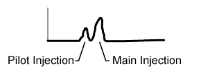
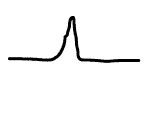
Combustion Pressure 
-
During pilot injection, the pilot injection volume, timing, and interval (between pilot injection and main injection) are controlled as shown below:
-
-
Glow Plug Control
-
Except on the models compliant with EURO 5 emission regulations, the ECM controls the length of time for which the current is applied to the glow plug relay when the engine starts in accordance with engine coolant temperature to control the length of time for which the current is applied to the glow plug assemblies.
-
On the models compliant with EURO 5 emission regulations, the ECM sends a signal to the glow plug controller, and the glow plug controller independently controls the length of time for which the current is applied to the glow plug assemblies in each cylinder in accordance with engine conditions. By independently and precisely controlling the temperature inside each cylinder, low emissions are achieved.
-
-
Diesel Throttle Control
-
The ECM controls the opening of the diesel throttle valve to reduce the noise caused when idling and decelerating, and the noise and vibrations caused when stopping the engine.
-
-
Swirl Control (Models Compliant with EURO 4 Emission Regulations and Models Compliant with EURO 2 Emission Regulations with Variable Nozzle Vane Type Turbocharger)
-
The ECM controls the swirl control valve position to improve torque in the low engine speed range and to optimize exhaust emissions.
-
-
Turbocharger Control (Models with Variable Nozzle Vane Type Turbocharger)
-
The ECM controls the nozzle vane position, in order to obtain the calculated target turbo pressure appropriate to the engine operating conditions.
-
-
Oil Maintenance Management System (Models for Europe)
-
This system determines the deterioration conditions of the engine oil and illuminates an engine oil change reminder light to inform the driver when the engine oil and the oil filter must be changed. Accordingly, maintenance intervals (30000 km maximum) that correspond to the actual deterioration conditions of the engine oil have been achieved.
-
This system indirectly determines the deterioration of the engine oil based on the information provided by the ECM.
-
-
-
CONSTRUCTION
-
ECM
-
On the models compliant with EURO 5 emission regulations, the forest 2 type CPU of the ECM is used to increase the speed for processing the signals.
-
Except on the models compliant with EURO 5 emission regulations, the 32-bit CPU of the ECM is used to increase the speed for processing the signals.
-
The ECM of the 2KD-FTV engine and 2KD-FTV High Version engine contain engine programs that differ from each other. However, both engines share the same mechanical components.
-
-
Injector Driver
-
The injector driver is used to drive the injector at high speeds. The injector driver has achieved high-speed driving under high fuel pressure conditions through the use of a DC/DC converter that provides a high voltage, quick-charging system.
-
The ECM constantly monitors the injector driver and stops the engine when an abnormal condition is detected.
-
-
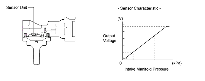
Turbo Pressure Sensor
-
The turbo pressure sensor consists of a semiconductor which utilizes the characteristics of a silicon chip that changes its electrical resistance when pressure is applied to it. The sensor converts the intake air pressure into an electrical signal, and sends it to the ECM in an amplified form.
-
-
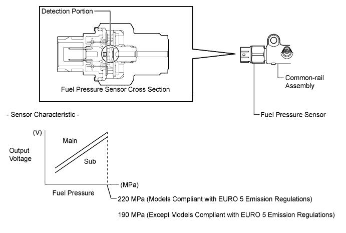
Fuel Pressure Sensor
-
The fuel pressure sensor, which is mounted on the common-rail, outputs a signal that represents the fuel pressure in the common-rail to the ECM in order to constantly regulate the fuel at an optimal pressure.
-
The fuel pressure sensor consists of a semiconductor which utilizes the characteristics of a silicon chip that changes its electrical resistance when pressure is applied to it.
-
The fuel pressure sensor has 2 circuits (main and sub), which enable the ECM to constantly compare the values detected by the 2 circuits. As a result, highly precise values can be detected, which also enables a higher level of fail-safe control.
-
-
Pressure Discharge Valve
-
The pressure discharge valve regulates the fuel pressure. In the pressure discharge valve, the plunger opens and closes in accordance with the actuation signals from the injector driver. Thus, it regulates pressure by releasing excess pressure from the common-rail. In addition, it has a pressure reduction function in case of emergency.
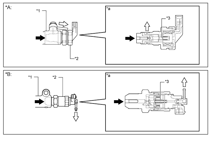
Text in Illustration *A Models Compliant with EURO 5 Emission Regulations *B Except Models Compliant with EURO 5 Emission Regulations *1 Common-rail Assembly *2 Pressure Discharge Valve *3 Plunger - - *a Pressure Discharge Valve Cross Section - - 
Fuel from Common-rail (High Pressure) 
Fuel to Fuel Tank (Excess Pressure)
-
-
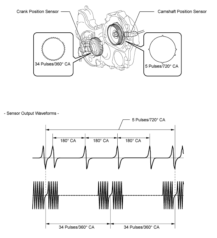
Crank Position Sensor and Camshaft Position Sensor
-
The timing rotor of the crankshaft consists of 34 teeth, with 2 teeth missing. The crank position sensor outputs the crankshaft rotation signals every 10°, and the missing teeth are used to determine the top dead center.
-
To detect the camshaft position, a protrusion that is provided on the timing pulley is used to generate 5 pulses for every 2 revolutions of the crankshaft.
-
-
Intake Mass Air Flow Meter Sub-assembly (Models Compliant with EURO 5, EURO 4 and EURO 2 Emission Regulations)
-
This engine uses the hot-wire type air flow meter designed for direct electrical measurement of the intake air mass flow.
-
This intake mass air flow meter sub-assembly has a built-in intake air temperature sensor.
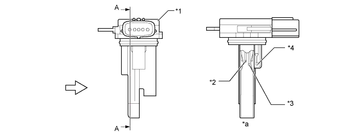
Text in Illustration (Models Compliant with EURO 5 Emission Regulations:) *1 Intake Mass Air Flow Meter Sub-assembly *2 Platinum Hot-wire Element *3 Temperature Sensing Element *4 Intake Air Temperature Sensor *a A - A Cross Section - - Air Flow - - 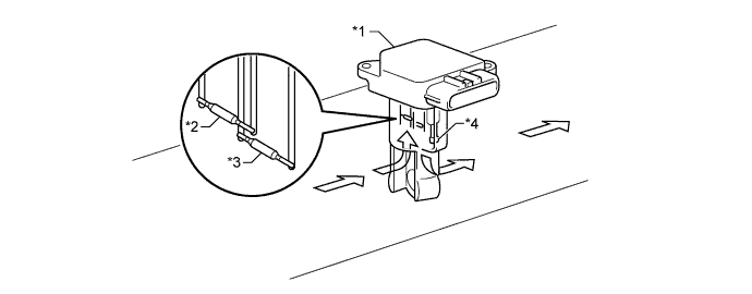
Text in Illustration (Models Compliant with EURO 4 and EURO 2 Emission Regulations:) *1 Intake Mass Air Flow Meter Sub-assembly *2 Temperature Sensing Element *3 Platinum Hot-wire Element *4 Intake Air Temperature Sensor Air Flow - -
-
-
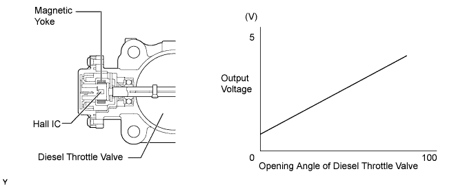
Throttle Position Sensor
-
The throttle position sensor is mounted on the diesel throttle body assembly. To detect the opening angle of the diesel throttle valve, the throttle position sensor converts the magnetic flux density, that changes when the magnetic yoke (located on the same axis as the diesel throttle valve shaft) rotates around the Hall IC, into electric signals to operate the throttle control motor.
-
-
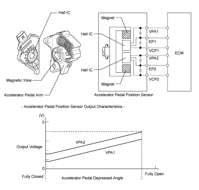
Accelerator Pedal Position Sensor
-
The magnetic yoke that is mounted at the base of the accelerator pedal arm moves around the Hall IC in accordance with the amount of effort that is applied to the accelerator pedal. The Hall IC converts the changes in the magnetic flux that occur at that time into electrical signals, and outputs them in the form of accelerator pedal effort to the ECM.
-
-
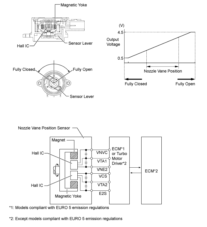
Nozzle Vane Position Sensor (Models with Variable Nozzle Vane Type Turbocharger)
-
The nozzle vane position sensor consists of a Hall IC and a magnetic yoke that rotates in unison with the movement of the linkage that actuates the nozzle vane. The nozzle vane position sensor converts the changes in the magnetic flux that are caused by the rotation of the DC motor (hence, the rotation of the magnetic yoke) into electric signals, and outputs them to the ECM (via the turbo motor driver*). The ECM determines the actual nozzle vane position from the electric signals in order to calculate the target nozzle vane position.
-
*: Except models compliant with EURO 5 emission regulations
-
-
-
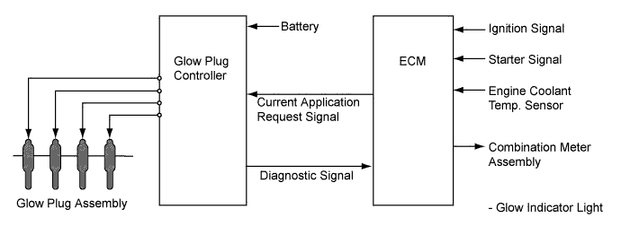
Glow Plug Controller (Models Compliant with EURO 5 Emission Regulations)
-
The glow plug controller independently controls the length of time for which the current is applied to the glow plug assemblies in accordance with signals from the ECM in each cylinder.
-
The glow plug controller has a function to detect open circuits in the glow plug assemblies. When the glow plug controller detects an open circuit in a glow plug assembly, it sends a signal to the ECM.
-
-
-
OPERATION
-
Glow Plug Control
-
On the models compliant with EURO 5 emission regulations, glow plug control carries out the following controls:
-
When the ignition switch is turned from off to ON, the ECM sends a signal to the glow plug controller. Based on this signal, the glow plug controller heats the glow plug assemblies rapidly. At this moment, the glow indicator light in the combination meter is illuminated to inform the driver that the glow plug assemblies are being heated.
-
When the engine starts and the starter signal is off, after-glow control is conducted.
-
In accordance with signals from the ECM, the glow plug controller independently applies current via the glow plug assembly in each cylinder to control the temperature of each cylinder independently.
-
When the glow plug controller detects a malfunction in the glow circuit, it sends a diagnostic signal to the ECM.
-
While the catalyst support control is in operation, the ECM sends a signal to the glow plug controller to heat the glow plug assembly. For details of catalyst support control, see the 2KD-FTV Emission Control section.
-
-
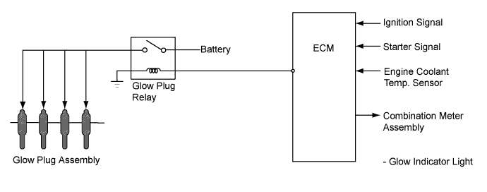
Except on the models compliant with EURO 5 emission regulations, glow plug control carries out the following controls:
-
When the ignition switch is turned from off to ON, the ECM operates the glow plug relay to heat the glow plug assemblies rapidly. At that moment, the glow indicator light in the combination meter assembly is illuminated to inform the driver that the glow plug assemblies are being heated.
-
When the engine starts and the starter signal is off, after-glow control is conducted. When the temperature of the glow plug assembly reaches a predetermined level during after-glow control, it is maintained at a nearly constant level using the self-temperature-controlling function of the glow plug assembly.
-
-
-
Diesel Throttle Control
-
The opening of the diesel throttle valve is controlled by the ECM in accordance with the engine conditions. As a result, the noise that is generated during idling and deceleration, as well as the noise and vibrations that are generated when the engine is stopped, have been reduced and this control makes it possible to recirculate the exhaust gas in accordance with the driving conditions.
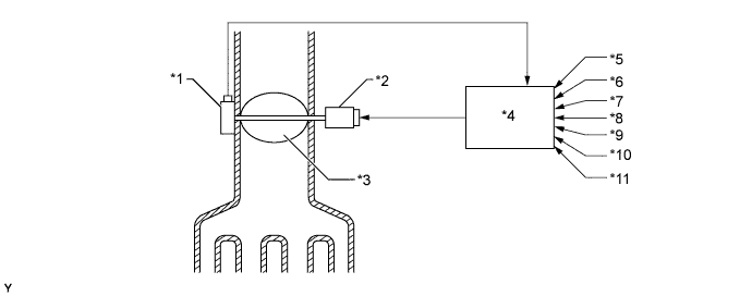
Text in Illustration *1 Throttle Position Sensor *2 Throttle Control Motor *3 Diesel Throttle Valve *4 ECM *5 Engine Speed Signal *6 Vehicle Speed Signal *7 Engine Coolant Temperature Signal *8 Intake Air Temperature Signal *9 Accelerator Pedal Position Signal *10 Intake Air Pressure Signal *11 Ignition Signal - -
-
-
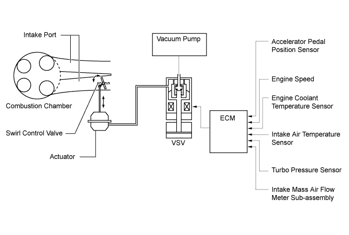
Swirl Control (Models Compliant with EURO 4 Emission Regulations and Models Compliant with EURO 2 Emission Regulations with Variable Nozzle Vane Type Turbocharger)
-
The ECM determines the swirl control valve position based on the engine conditions (engine speed and accelerator pedal effort). Then, it switches the vacuum applied to the actuator diaphragm via the VSV, in order to open and close the swirl control valve.
-
On a cold engine, the ECM fully closes the swirl control valve to reduce the amount of white smoke emissions.
-
In the low engine speed range, the ECM closes the swirl control valve to strengthen the swirl in the combustion chamber, thus promoting the mixture of fuel and air and stabilizing combustion.
-
When the engine speed increases to the low or middle-speed range, the ECM fully opens the swirl control valve.
-
-
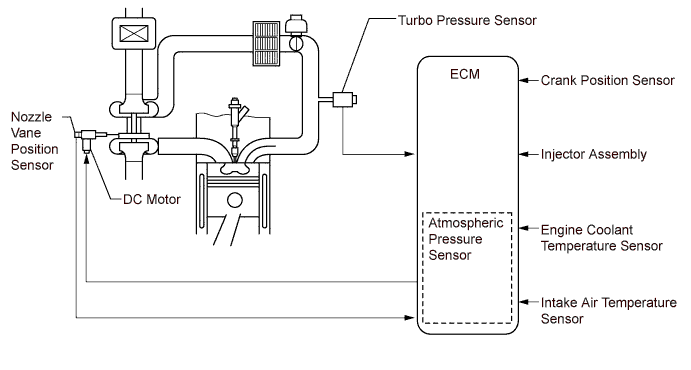
Turbocharger Control (Models with Variable Nozzle Vane Type Turbocharger)
-
On the models compliant with EURO 5 emission regulations, turbocharger control carries out the following controls:
-
The ECM calculates the optimal nozzle vane position in accordance with the driving conditions (engine speed, injection volume, atmospheric pressure, and engine coolant temperature etc.), and controls the nozzle vane position in accordance with the optimal nozzle vane position and the actual nozzle vane position signal provided by the nozzle vane position sensor.
-
-
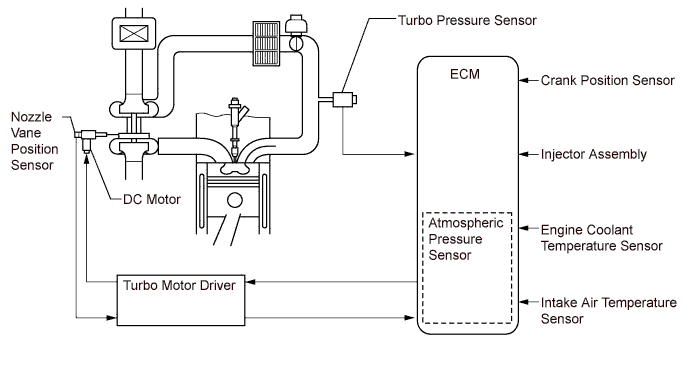
Except on the models compliant with EURO 5 emission regulations, turbocharger control carries out the following controls:
-
The ECM controls the nozzle vane position using the turbo motor driver, in order to obtain the calculated target turbo pressure appropriate to the engine operating conditions.
-
The ECM calculates the optimal nozzle vane position in accordance with the driving conditions (engine speed, injection volume, atmospheric pressure, and engine coolant temperature etc.), and sends a target nozzle vane position signal to the turbo motor driver. The turbo motor driver controls the nozzle vane position in accordance with this signal and the actual nozzle vane position signal provided by the nozzle vane position sensor.
-
-
-
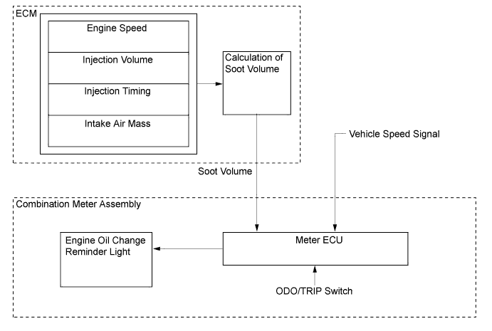
Oil Maintenance Management System (Models for Europe)
-
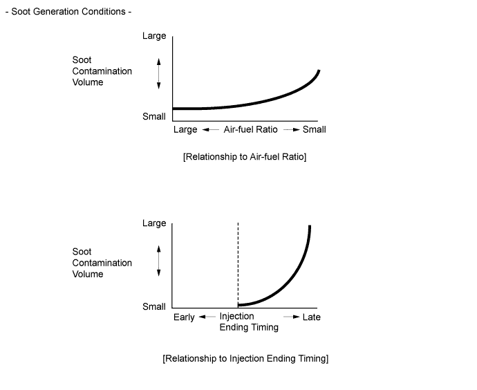
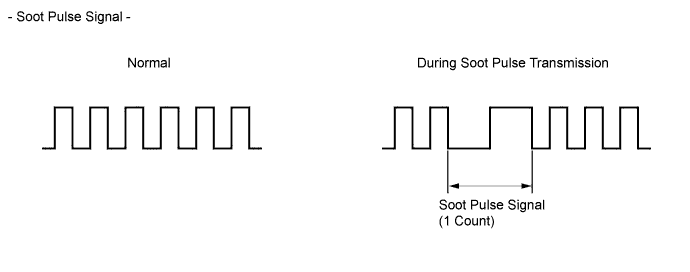
This system determines the deterioration of the engine oil and oil filter in accordance with the soot volume in the engine oil and oil filter. The ECM calculates the soot volume in the engine oil and oil filter in accordance with the engine speed, injection timing, injection volume, and air-fuel ratio. The ECM converts the soot volume into pulse signals and transmits the signals to the meter ECU. The meter ECU counts the pulse signals as the soot volume, and blinks an engine oil change reminder light when the cumulative value gets closer to a predetermined value, and illuminates the reminder light when the cumulative value reaches the predetermined value. Thus, this system informs the driver that the engine oil and the oil filter must be changed.
-
In addition to controlling the illumination of the engine oil change reminder light by calculating the soot volume, the ECM blinks the reminder light when the vehicle travel distance reaches 25000 km, and illuminates it when the travel distance reaches 30000 km. Thus, this function enhances the reliability of the system.
Tech Tips
-
This system does not determine the deterioration of the engine oil based on the elapsed time. Even if the engine oil change reminder light does not illuminate, the engine oil and oil filter should be changed at 2-year intervals at the maximum.
-
-
-