REAR DOOR LOCK(for Smart Cab) INSTALLATION
CAUTION / NOTICE / HINT
Tech Tips
-
Use the same procedure for the RH and LH sides.
-
The procedure listed below is for the LH side.
-
A bolt without a torque specification is shown in the standard bolt chart.
PROCEDURE
-
INSTALL LOWER ACCESS PANEL LOCK ASSEMBLY LH
-
Apply MP grease to the rotating and sliding areas of the lower access panel lock assembly LH.
-
Attach the hook.
-
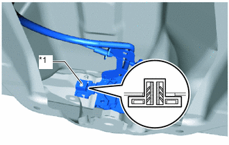
*1 Grommet Attach the grommet to the stud bolt to install the lower access panel lock assembly LH.
-
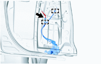
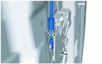
Connect the cable to the access panel lock remote control assembly LH and attach the clamp.
-
Connect the connector and attach the clamp.
-
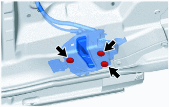
Using a T30 "TORX" socket wrench, install the 3 bolts.
- Torque:
- 5.0 N*m { 51 kgf*cm, 44 in.*lbf }
-
-
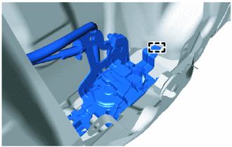
INSTALL UPPER ACCESS PANEL LOCK ASSEMBLY LH
-
Apply MP grease to the rotating and sliding areas of the upper access panel lock assembly LH.
-
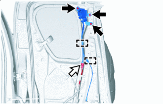

Bolt 
Connector Install the upper access panel lock assembly LH with the 3 bolts.
- Torque:
- 12 N*m { 122 kgf*cm, 9 ft.*lbf }
-
Connect the connector.
-
Attach the clamp and connect the cable to the access panel lock remote control assembly LH.
-
-
INSTALL REAR DOOR FRAME GARNISH LH
-
INSTALL FRONT SEAT OUTER BELT ASSEMBLY LH
-
INSTALL SEAT BELT ANCHOR COVER CAP
-
INSTALL REAR DOOR TRIM BOARD SUB-ASSEMBLY LH
-
INSTALL LAP BELT OUTER ANCHOR COVER
-
CONNECT CABLE TO NEGATIVE BATTERY TERMINAL (w/ Airbag System)
Note
When disconnecting the cable, some systems need to be initialized after the cable is reconnected.
-
CHECK SRS WARNING LIGHT (w/ Airbag System)
for Type A:
for Type B:
for Type C: