STEERING KNUCKLE REMOVAL
CAUTION / NOTICE / HINT
Use the same procedures for the RH side and LH side.
The procedures listed below are for the LH side.
PROCEDURE
REMOVE FRONT WHEEL
REMOVE FRONT AXLE SHAFT NUT LH
DISCONNECT FRONT SPEED SENSOR LH
REMOVE FRONT FLEXIBLE HOSE
REMOVE DISC BRAKE CYLINDER ASSEMBLY LH
REMOVE FRONT DISC
DISCONNECT TIE ROD END SUB-ASSEMBLY LH
DISCONNECT FRONT NO. 1 SUSPENSION LOWER ARM SUB-ASSEMBLY LH
REMOVE FRONT AXLE ASSEMBLY LH
REMOVE FRONT LOWER BALL JOINT ASSEMBLY LH
Hold the front axle assembly in a vise between aluminum plates.
Note:When using a vise, do not overtighten it.
Remove the cotter pin and nut.
-
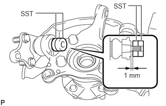
Install SST to the front lower ball joint as shown in the illustration.
09960-20010
09961-02050
09961-02050
Note:Make sure that the clearance measurement between SST and the front axle assembly is 1 mm (0.0394 in.).
-
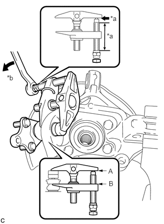
Using SST, remove the front lower ball joint from the front axle assembly as shown in the illustration.
09960-20010
09961-02050
09961-02050
09961-02010
Table 1. Text in Illustration *a
Molybdenum Grease Application Area
*b
Turn
CAUTION:Apply molybdenum grease to the bolt threads and the tip of SST.
Note:Install SST so that A and B are parallel.
Be sure to turn the part indicated in the illustration with a wrench.
Do not damage the front lower ball joint dust cover.
Be sure to tie the string of SST to the vehicle to prevent SST from dropping.
REMOVE STEERING KNUCKLE LH
Hold the front axle assembly in a vise between aluminum plates.
Note:When using a vise, do not overtighten it.
-
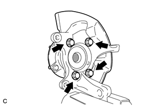
Remove the 4 bolts and front axle hub sub-assembly from the steering knuckle.
Note:Do not place the magnet rotor side of the hub and bearing so that it is facing downward, and do not allow the magnet rotor side to become damaged or contact foreign matter.
Remove the front brake dust cover from the steering knuckle.