CLUTCH UNIT(for Diesel) INSTALLATION
PROCEDURE
INSTALL CLUTCH DISC ASSEMBLY
-
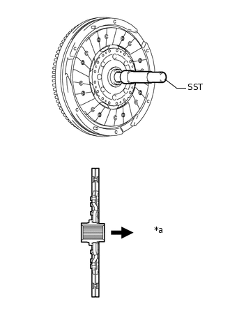
*a
Transaxle side
Insert SST into the clutch disc assembly, and then insert them into the flywheel.
09301-00310
Note:Do not insert the clutch disc assembly in the wrong direction.
-
INSTALL CLUTCH COVER ASSEMBLY
-
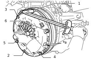
*a
Matchmark
Align the matchmarks on the clutch cover assembly with the one on the flywheel.
Tighten the 6 bolts uniformly in the order shown in the illustration, starting with the bolt located near the knock pin on the top.
19 N*m
194 kgf*cm
14 ft.*lbf
Note:Following the order in the illustration, make sure to uniformly tighten the bolts 180°.
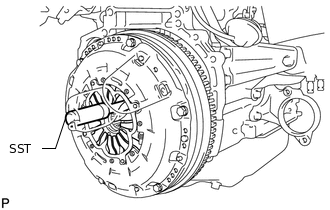
After checking that the disc is in the center, gently move SST up and down, and right and left to tighten the bolts.
-
INSPECT AND ADJUST CLUTCH COVER ASSEMBLY
-
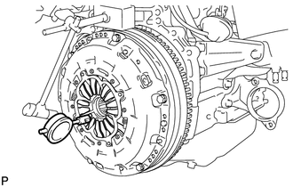
Using a dial indicator with a roller instrument, measure the diaphragm spring tip alignment.
Maximum misalignment
1.3 mm (0.0512 in.)
If the alignment is not as specified, using SST, adjust the diaphragm spring tip alignment.
09333-00013
-
INSTALL RELEASE FORK SUPPORT
-
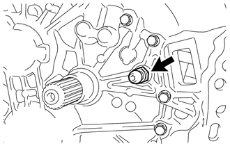
Install the release fork support to the manual transaxle assembly.
47 N*m
479 kgf*cm
35 ft.*lbf
-
INSTALL CLUTCH RELEASE FORK BOOT
-
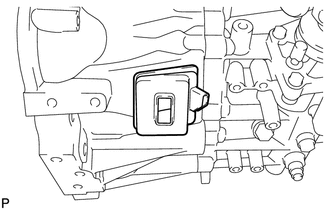
Install the clutch release fork boot onto the manual transaxle assembly.
-
INSTALL CLUTCH RELEASE FORK SUB-ASSEMBLY
-

Multemp 8158 grease or equivalent
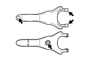
Apply Multemp 8158 grease or equivalent to the following areas:
The surfaces on the clutch release fork sub-assembly that contact the clutch release bearing.
The surfaces on the clutch release fork sub-assembly that contact the push rod of the clutch release fork support.
The surfaces on the clutch release fork sub-assembly that contact the clutch release fork support.
Grease
Multemp 8158 grease or equivalent
Install the clutch release fork sub-assembly to the clutch release bearing.
-
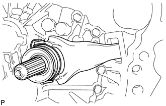
INSTALL CLUTCH RELEASE BEARING ASSEMBLY
-
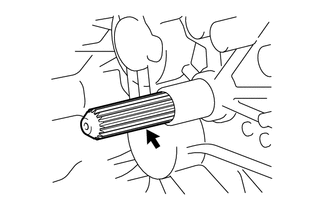
Toyota Genuine Clutch Spline Grease or equivalent
Apply clutch spline grease to the input shaft spline.
Grease
Toyota Genuine Clutch Spline Grease or equivalent
-
Install the clutch release bearing with clutch release fork sub-assembly to the manual transaxle assembly.
Note:After the installation, move the fork forward and backward to check that the release bearing slides smoothly.
-
INSTALL MANUAL TRANSAXLE ASSEMBLY