СТАРТЕР (для моделей мощностью 1,6 кВт) ПОВТОРНАЯ СБОРКА
Tech Tips
Use high-temperature-resistant grease to lubricate the bearings and sliding parts when assembling the starter.
-
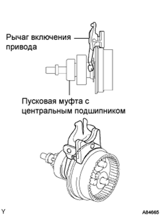
INSTALL STARTER CENTER BEARING CLUTCH SUB-ASSEMBLY
-
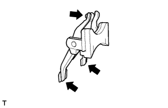
Apply high-temperature grease to the starter drive lever set pin, as shown in the illustration.
-
Install the drive lever set pin to the starter center bearing clutch sub-assembly.
-
Install the starter center bearing clutch and drive lever set pin together to the starter drive housing.
-
-
INSTALL PLANETARY GEAR
-
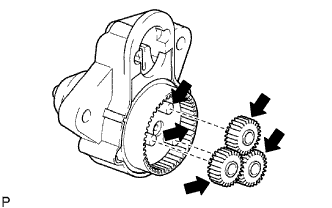
Apply high-temperature grease to the planetary gears and pin parts of the planetary shaft.
-
Install the 3 planetary gears onto the pins of the planetary shaft.
-
-
INSTALL STARTER ARMATURE ASSEMBLY
Note
Do not drop the starter armature assembly.
-
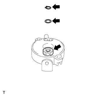
Apply high-temperature grease to the plate washer, a new snap ring and the bearing, as shown in the illustration.
-
Hold the starter commutator end frame between aluminum plates in a vise.
Note
Do not damage the starter commutator end frame.
-
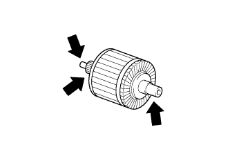
Apply high-temperature grease to the starter armature assembly, as shown in the illustration.
-
Install the starter armature assembly to the starter commutator end frame assembly.
-
Install the plate washer to the starter armature shaft.
-
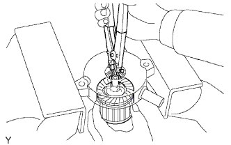
Using snap ring pliers, install the snap ring.
Note
-
Be sure to install the snap ring in the armature shaft groove securely.
-
Be sure to properly install the snap ring because it easily expands.
-
-
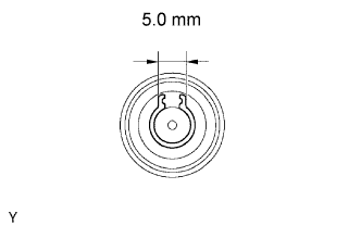
Check the snap ring length.
-
Using a vernier caliper, measure the snap ring length.
Maximum length 5.0 mm (0.197 in.) If the length is greater than the maximum, replace the snap ring.
-
-
-
INSTALL STARTER COMMUTATOR END FRAME COVER
-
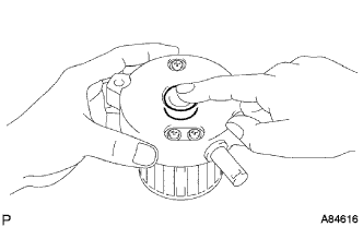
Install the commutator end frame cover into the starter commutator end frame.
-
-
INSTALL STARTER ARMATURE PLATE
-
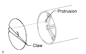
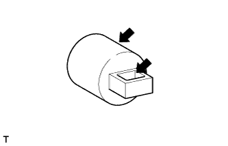
Align the claws of the armature plate with the protrusion inside the starter yoke, and install the starter armature plate.
-
-
INSTALL STARTER COMMUTATOR END FRAME ASSEMBLY
-
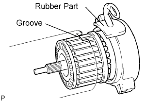
Align the rubber part on the starter commutator end frame with the groove of the starter yoke.
-
Install the starter commutator end frame to the starter yoke.
Note
The magnet of the starter yoke may attract the starter armature when the starter commutator end frame is installed, causing the magnet to break.
-
-
INSTALL STARTER YOKE ASSEMBLY
-
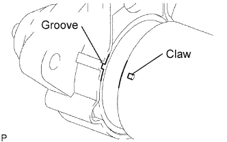
Align the claw of the starter yoke with the groove inside the starter drive housing.
-
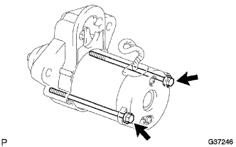
Install the starter yoke with the 2 bolts.
- Torque:
- 6.0 N*m { 61 kgf*cm, 53 in.*lbf }
-
-
INSTALL REPAIR SERVICE STARTER KIT
-
Apply high-temperature grease to the plunger and hook, as shown in the illustration.
-
Hang the plunger hook of the repair service starter kit on the drive lever set pin.
-
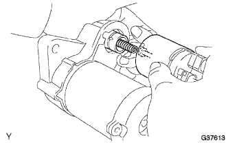
Install the plunger and return spring.
-
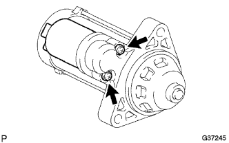
Install the repair service starter kit with the 2 screws.
- Torque:
- 7.5 N*m { 77 kgf*cm, 66 in.*lbf }
-
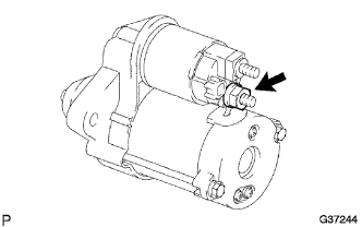
Connect the lead wire to the terminal with the nut.
- Torque:
- 10 N*m { 102 kgf*cm, 7 ft.*lbf }
-