SFI SYSTEM Starter Signal Circuit
DESCRIPTION
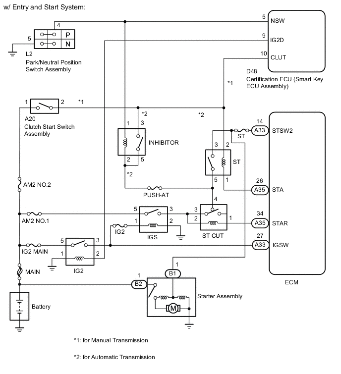
- w/ Entry and Start System
While the engine is being cranked, the ECM detects the current from the ST relay drive circuit to the STSW2 and STA terminals, and carries out engine control when starting (STSW2 signal and STA signal). The ECM drives the ST relay until the engine start signal is input from the certification ECU (smart key ECU assembly), and drives the starter until a complete engine start is detected.
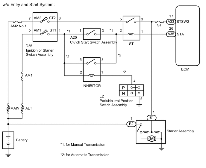
- w/o Entry and Start System
While the engine is being cranked, the current from the ST relay flows to the ECM STSW2 terminal.
WIRING DIAGRAM
CAUTION / NOTICE / HINT
Note
Inspect the fuses for circuits related to this system before performing the following inspection procedure.
PROCEDURE
-
CHECK WHETHER ENGINE CAN BE CRANKED
-
Check if the engine can be cranked.
Result Result Proceed to Engine cannot be cranked A Engine can be cranked (w/ Entry and Start System) B Engine can be cranked (w/o Entry and Start System) C
B 
READ VALUE USING GTS (STARTER SIGNAL) Click here
C
READ VALUE USING GTS (ST SIGNAL) Click here
A 
-
-
READ VALUE USING GTS (STARTER SIGNAL)
-
Connect the GTS to DLC3.
-
Turn the ignition switch to ON.
-
Turn the GTS on.
-
Enter the following menus: Powertrain / Engine / Data List / Starter Signal.
-
Check the value displayed on the GTS when the ignition switch is turned to the ON and START positions.
OK Ignition Switch Position Starter Signal ON Close (OFF) START Open (ON) Result Result Proceed to OK (w/ Entry and Start System) A NG (w/ Entry and Start System) B OK (w/o Entry and Start System) C NG (w/o Entry and Start System) D
B
READ VALUE USING GTS (STARTER CUT RELAY) Click here
C
CHECK HARNESS AND CONNECTOR (ECM - ST RELAY - STARTER ASSEMBLY) Click here
D
INSPECT IGNITION OR STARTER SWITCH ASSEMBLY Click here
A
-
-
CHECK HARNESS AND CONNECTOR (ST RELAY - ECM - STARTER ASSEMBLY)
-
Disconnect the ECM connector.
-
Remove the ST relay from the engine room relay block assembly.
-
Disconnect the starter assembly connector.
-
Measure the resistance according to the value(s) in the table below.
Standard Resistance (Check for open) Tester Connection Condition Specified Condition A33-14 (STSW2) - B1-1 Always Below 1 Ω ST relay terminal 3 - B1-1 Always Below 1 Ω Standard Resistance (Check for short) Tester Connection Condition Specified Condition A33-14 (STSW2), B1-1 or ST relay terminal 3 - Body ground Always 10 kΩ or higher
NG 
REPAIR OR REPLACE HARNESS OR CONNECTOR
OK
-
-
READ VALUE USING GTS (STARTER CUT RELAY)
-
Connect the GTS to DLC3.
-
Turn the ignition switch to ON.
-
Turn the GTS on.
-
Enter the following menus: Powertrain / Engine / Data List / Starter Cut Relay.
-
Check the value displayed on the GTS when the ignition switch is turned to the ON and START positions.
OK Ignition Switch Position Starter Cut Relay ON OFF START ON Result Result Proceed to NG A OK (for automatic transmission models) B OK (for manual transmission models) C
B
INSPECT PARK/NEUTRAL POSITION SWITCH ASSEMBLY Click here
C
INSPECT CLUTCH START SWITCH ASSEMBLY Click here
A
-
-
CHECK HARNESS AND CONNECTOR (ECM - ST CUT RELAY)
-
Disconnect the ECM connector.
-
Remove the ST CUT relay from the engine room relay block assembly.
-
Measure the resistance according to the value(s) in the table below.
Standard Resistance (Check for open) Tester Connection Condition Specified Condition A35-34 (STAR) - ST CUT relay terminal 1 Always Below 1 Ω Standard Resistance (Check for short) Tester Connection Condition Specified Condition A35-34 (STAR) or ST CUT relay terminal 1 - Body ground Always 10 kΩ or higher
NG
REPAIR OR REPLACE HARNESS OR CONNECTOR
OK
-
-
CHECK HARNESS AND CONNECTOR (IGS RELAY - ST CUT RELAY - BODY GROUND)
-
Remove the ST CUT relay and IGS relay from the engine room relay block assembly.
-
Measure the resistance according to the value(s) in the table below.
Standard Resistance (Check for open) Tester Connection Condition Specified Condition ST CUT relay terminal 3 - IGS relay terminal 3 Always Below 1 Ω ST CUT relay terminal 2 - IGS relay terminal 3 Always Below 1 Ω IGS relay terminal 2 - Body ground Always Below 1 Ω Standard Resistance (Check for short) Tester Connection Condition Specified Condition ST CUT relay terminal 3, ST CUT relay terminal 2 or IGS relay terminal 3 - Body ground Always 10 kΩ or higher
NG
REPAIR OR REPLACE HARNESS OR CONNECTOR
OK
-
-
INSPECT TERMINAL VOLTAGE (IGS RELAY)
-
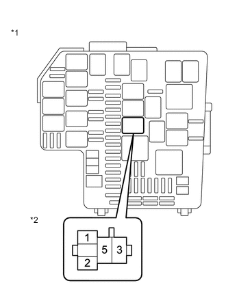
Text in Illustration *1 Engine Room Relay Block Assembly *2 IGS Relay Terminal Remove the IGS relay from the engine room relay block assembly.
-
Measure the voltage according to the value(s) in the table below.
Standard Voltage Tester Connection Condition Specified Condition IGS relay terminal 5 - Body ground Always 11 to 14 V
NG
REPAIR OR REPLACE HARNESS OR CONNECTOR
OK
-
-
CHECK HARNESS AND CONNECTOR (ECM - IG2 RELAY - IGS RELAY)
-
Disconnect the ECM connector.
-
Remove the IG2 relay and IGS relay from the engine room relay block assembly.
-
Measure the resistance according to the value(s) in the table below.
Standard Resistance (Check for open) Tester Connection Condition Specified Condition A33-27 (IGSW) - IG2 relay terminal 3 Always Below 1 Ω IG2 relay terminal 3 - IGS relay terminal 1 Always Below 1 Ω Standard Resistance (Check for short) Tester Connection Condition Specified Condition A33-27 (IGSW), IG2 relay terminal 3 or IGS relay terminal 1 - Body ground Always 10 kΩ or higher
OK
GO TO ENTRY AND START SYSTEM (for Start Function) Click here
NG
REPAIR OR REPLACE HARNESS OR CONNECTOR
-
-
INSPECT PARK/NEUTRAL POSITION SWITCH ASSEMBLY
-
Inspect the park/neutral position switch assembly Click here.
NG
REPLACE PARK/NEUTRAL POSITION SWITCH ASSEMBLY Click here
OK
-
-
CHECK HARNESS AND CONNECTOR (SMART KEY ECU - PARK/NEUTRAL POSITION SWITCH)
-
Disconnect the park/neutral position switch assembly connector.
-
Disconnect the smart key ECU assembly connector.
-
Remove the INHIBITOR relay from the engine room relay block assembly.
-
Measure the resistance according to the value(s) in the table below.
Standard Resistance (Check for open) Tester Connection Condition Specified Condition L2-4 - D48-5 (NSW) Always Below 1 Ω L2-4 - INHIBITOR relay terminal 1 Always Below 1 Ω L2-5 - Body ground Always Below 1 Ω Standard Resistance (Check for short) Tester Connection Condition Specified Condition L2-4, D48-5 (NSW) or INHIBITOR relay terminal 1 - Body ground Always 10 kΩ or higher
NG
REPAIR OR REPLACE HARNESS OR CONNECTOR
OK
-
-
CHECK HARNESS AND CONNECTOR (ST CUT RELAY - INHIBITOR RELAY - ST RELAY)
-
Remove the ST relay, ST CUT relay and INHIBITOR relay from the engine room relay block assembly.
-
Measure the resistance according to the value(s) in the table below.
Standard Resistance (Check for open) Tester Connection Condition Specified Condition ST CUT relay terminal 4 - INHIBITOR relay terminal 2 Always Below 1 Ω ST CUT relay terminal 4 - INHIBITOR relay terminal 5 Always Below 1 Ω ST CUT relay terminal 4 - ST relay terminal 5 Always Below 1 Ω Standard Resistance (Check for short) Tester Connection Condition Specified Condition ST CUT relay terminal 4, INHIBITOR relay terminal 2, INHIBITOR relay terminal 5 or ST relay terminal 5 - Body ground Always 10 kΩ or higher
NG
REPAIR OR REPLACE HARNESS OR CONNECTOR
OK
-
-
CHECK HARNESS AND CONNECTOR (INHIBITOR RELAY - ST RELAY)
-
Remove the ST relay and INHIBITOR relay from the engine room relay block assembly.
-
Measure the resistance according to the value(s) in the table below.
Standard Resistance (Check for open) Tester Connection Condition Specified Condition INHIBITOR relay terminal 3 - ST relay terminal 2 Always Below 1 Ω Standard Resistance (Check for short) Tester Connection Condition Specified Condition INHIBITOR relay terminal 3 or ST relay terminal 2 - Body ground Always 10 kΩ or higher
NG
REPAIR OR REPLACE HARNESS OR CONNECTOR
OK
-
-
CHECK HARNESS AND CONNECTOR (ECM - ST RELAY)
-
Disconnect the ECM connector.
-
Remove the ST relay from the engine room relay block assembly.
-
Measure the resistance according to the value(s) in the table below.
Standard Resistance (Check for open) Tester Connection Condition Specified Condition A35-26 (STA) - ST relay terminal 1 Always Below 1 Ω Standard Resistance (Check for short) Tester Connection Condition Specified Condition A35-26 (STA) or ST relay terminal 1 - Body ground Always 10 kΩ or higher
OK
GO TO ENTRY AND START SYSTEM (for Start Function) Click here
NG
REPAIR OR REPLACE HARNESS OR CONNECTOR
-
-
INSPECT CLUTCH START SWITCH ASSEMBLY
-
Inspect the clutch start switch assembly (for LHD) Click here.
-
Inspect the clutch start switch assembly (for RHD) Click here.
Result Result Proceed to OK A NG (for LHD) B NG (for RHD) C
B
REPLACE CLUTCH START SWITCH ASSEMBLY Click here
C
REPLACE CLUTCH START SWITCH ASSEMBLY Click here
A
-
-
INSPECT TERMINAL VOLTAGE (+B OF CLUTCH START SWITCH ASSEMBLY)
-
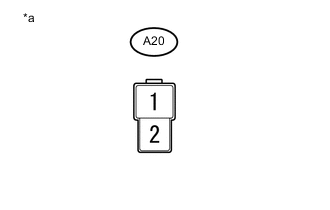
Text in Illustration *a Front view of wire harness connector
(to Clutch Start Switch Assembly)
Disconnect the clutch start switch assembly connector.
-
Measure the voltage according to the value(s) in the table below.
Standard Voltage Tester Connection Condition Specified Condition A20-1 - Body ground Always 11 to 14 V
NG
REPAIR OR REPLACE HARNESS OR CONNECTOR
OK
-
-
CHECK HARNESS AND CONNECTOR (CLUTCH START SWITCH - ST RELAY - SMART KEY ECU ASSEMBLY)
-
Disconnect the clutch start switch assembly connector.
-
Remove the ST relay from the engine room relay block assembly.
-
Disconnect the smart key ECU assembly connector.
-
Measure the resistance according to the value(s) in the table below.
Standard Resistance (Check for Open) Tester Connection Condition Specified Condition A20-2 - ST relay terminal 2 Always Below 1 Ω A20-2 - D48-10 (CLUT) Always Below 1 Ω Standard Resistance (Check for short) Tester Connection Condition Specified Condition A20-2, D48-10 (CLUT), or ST relay terminal 2 - Body ground Always 10 kΩ or higher
NG
REPAIR OR REPLACE HARNESS OR CONNECTOR
OK
-
-
CHECK HARNESS AND CONNECTOR (ST RELAY - ST CUT RELAY)
-
Remove the ST relay and ST CUT relay from the engine room relay block assembly.
-
Measure the resistance according to the value(s) in the table below.
Standard Resistance (Check for Open) Tester Connection Condition Specified Condition ST relay terminal 5 - ST CUT relay terminal 4 Always Below 1 Ω Standard Resistance (Check for short) Tester Connection Condition Specified Condition ST relay terminal 5 or ST CUT relay terminal 4 - Body ground Always 10 kΩ or higher
NG
REPAIR OR REPLACE HARNESS OR CONNECTOR
OK
-
-
CHECK HARNESS AND CONNECTOR (ECM - ST RELAY)
-
Disconnect the ECM connector.
-
Remove the ST relay from the engine room relay block assembly.
-
Measure the resistance according to the value(s) in the table below.
Standard Resistance (Check for open) Tester Connection Condition Specified Condition A35-26 (STA) - ST relay terminal 1 Always Below 1 Ω A33-14 (STSW2) - ST relay terminal 3 Always Below 1 Ω Standard Resistance (Check for short) Tester Connection Condition Specified Condition A35-26 (STA), A33-14 (STSW2), ST relay terminal 1 or ST relay terminal 3 - Body ground Always 10 kΩ or higher
OK
REPLACE ECM Click here
NG
REPAIR OR REPLACE HARNESS OR CONNECTOR
-
-
READ VALUE USING GTS (STARTER SIGNAL)
-
Connect the GTS to DLC3.
-
Turn the ignition switch to ON.
-
Turn the GTS on.
-
Enter the following menus: Powertrain / Engine / Data List / Starter Signal.
-
Check the value displayed on the GTS when the ignition switch is turned to the ON and START positions.
OK Ignition Switch Position Starter Signal ON Close (OFF) START Open (ON) Result Result Proceed to NG A OK B
B
PROCEED TO NEXT SUSPECTED AREA SHOWN IN PROBLEM SYMPTOMS TABLE Click here
A
-
-
CHECK HARNESS AND CONNECTOR (ECM - ST RELAY)
-
Disconnect the ECM connector.
-
Remove the ST relay from the engine room relay block assembly.
-
Measure the resistance according to the value(s) in the table below.
Standard Resistance (Check for open) Tester Connection Condition Specified Condition A35-26 (STA) - ST relay terminal 1 Always Below 1 Ω A33-14 (STSW2) - ST relay terminal 3 Always Below 1 Ω Standard Resistance (Check for short) Tester Connection Condition Specified Condition A35-26 (STA), A33-14 (STSW2), ST relay terminal 1 or ST relay terminal 3 - Body ground Always 10 kΩ or higher
OK
REPLACE ECM Click here
NG
REPAIR OR REPLACE HARNESS OR CONNECTOR
-
-
CHECK HARNESS AND CONNECTOR (ECM - ST RELAY - STARTER ASSEMBLY)
-
Disconnect the ECM connector.
-
Disconnect the starter assembly connector.
-
Remove the ST relay from the engine room relay block assembly.
-
Measure the resistance according to the value(s) in the table below.
Standard Resistance (Check for open) Tester Connection Condition Specified Condition B1-1 - A33-17 (STSW2) Always Below 1 Ω B1-1 - ST relay terminal 3 Always Below 1 Ω Standard Resistance (Check for short) Tester Connection Condition Specified Condition A33-17 (STSW2), ST relay terminal 3 or B1-1 - Body ground Always 10 kΩ or higher
NG
REPAIR OR REPLACE HARNESS OR CONNECTOR
OK
-
-
INSPECT IGNITION OR STARTER SWITCH ASSEMBLY
-
Inspect the ignition or starter switch assembly Click here.
NG
REPLACE IGNITION OR STARTER SWITCH ASSEMBLY Click here
OK
-
-
CHECK HARNESS AND CONNECTOR (IGNITION OR STARTER SWITCH ASSEMBLY - ST RELAY)
-
Disconnect the ignition or starter switch assembly connector.
-
Remove the ST relay from the engine room relay block assembly.
-
Measure the resistance according to the value(s) in the table below.
Standard Resistance (Check for open) Tester Connection Condition Specified Condition D55-8 (ST2) - ST relay terminal 5 Always Below 1 Ω Standard Resistance (Check for short) Tester Connection Condition Specified Condition D55-8 (ST2) or ST relay terminal 5 - Body ground Always 10 kΩ or higher
NG
REPAIR OR REPLACE HARNESS OR CONNECTOR
OK
-
-
INSPECT TERMINAL VOLTAGE (+B OF IGNITION OR STARTER SWITCH ASSEMBLY)
-
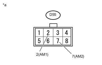
Text in Illustration *a Front view of wire harness connector
(to Ignition or Starter Switch Assembly)
Disconnect the ignition or starter switch assembly connector.
-
Measure the voltage according to the value(s) in the table below.
Standard Voltage Tester Connection Condition Specified Condition D55-2 (AM1) - Body ground Always 11 to 14 V D55-7 (AM2) - Body ground Always 11 to 14 V Result Result Proceed to NG A OK (for Automatic Transmission) B OK (for Manual Transmission) C
A
REPAIR OR REPLACE HARNESS OR CONNECTOR
C
INSPECT CLUTCH START SWITCH ASSEMBLY Click here
B
-
-
INSPECT PARK/NEUTRAL POSITION SWITCH ASSEMBLY
-
Inspect the park/neutral position switch assembly Click here.
NG
REPLACE PARK/NEUTRAL POSITION SWITCH ASSEMBLY Click here
OK
-
-
CHECK HARNESS AND CONNECTOR (PARK/NEUTRAL POSITION SWITCH ASSEMBLY - INHIBITOR RELAY)
-
Disconnect the park/neutral position switch assembly connector.
-
Remove the INHIBITOR relay from the engine room relay block assembly.
-
Measure the resistance according to the value(s) in the table below.
Standard Resistance (Check for open) Tester Connection Condition Specified Condition L2-4 - INHIBITOR relay terminal 1 Always Below 1 Ω L2-5 - Body ground Always Below 1 Ω Standard Resistance (Check for short) Tester Connection Condition Specified Condition L2-4 or INHIBITOR relay terminal 1 - Body ground Always 10 kΩ or higher
NG
REPAIR OR REPLACE HARNESS OR CONNECTOR
OK
-
-
CHECK HARNESS AND CONNECTOR (IGNITION OR STARTER SWITCH ASSEMBLY - INHIBITOR RELAY)
-
Disconnect the ignition or starter switch assembly connector.
-
Remove the INHIBITOR relay from the engine room relay block assembly.
-
Measure the resistance according to the value(s) in the table below.
Standard Resistance (Check for open) Tester Connection Condition Specified Condition D55-1 (ST1) - INHIBITOR relay terminal 5 Always Below 1 Ω D55-1 (ST1) - INHIBITOR relay terminal 2 Always Below 1 Ω Standard Resistance (Check for short) Tester Connection Condition Specified Condition D55-1 (ST1), INHIBITOR relay terminal 2 or INHIBITOR relay terminal 5 - Body ground Always 10 kΩ or higher
NG
REPAIR OR REPLACE HARNESS OR CONNECTOR
OK
-
-
CHECK HARNESS AND CONNECTOR (INHIBITOR RELAY - ST RELAY)
-
Remove the INHIBITOR relay and ST relay from the engine room relay block assembly.
-
Measure the resistance according to the value(s) in the table below.
Standard Resistance (Check for open) Tester Connection Condition Specified Condition INHIBITOR relay terminal 3 - ST relay terminal 2 Always Below 1 Ω Standard Resistance (Check for short) Tester Connection Condition Specified Condition INHIBITOR relay terminal 3 or ST relay terminal 2 - Body ground Always 10 kΩ or higher
NG
REPAIR OR REPLACE HARNESS OR CONNECTOR
OK
-
-
CHECK HARNESS AND CONNECTOR (ECM - ST RELAY)
-
Disconnect the ECM connector.
-
Remove the ST relay from the engine room relay block assembly.
-
Measure the resistance according to the value(s) in the table below.
Standard Resistance (Check for open) Tester Connection Condition Specified Condition A35-26 (STA) - ST relay terminal 1 Always Below 1 Ω A33-17 (STSW2) - ST relay terminal 3 Always Below 1 Ω Standard Resistance (Check for short) Tester Connection Condition Specified Condition A35-26 (STA), A33-17 (STSW2), ST relay terminal 1 or ST relay terminal 3 - Body ground Always 10 kΩ or higher
OK
PROCEED TO NEXT SUSPECTED AREA SHOWN IN PROBLEM SYMPTOMS TABLE Click here
NG
REPAIR OR REPLACE HARNESS OR CONNECTOR
-
-
INSPECT CLUTCH START SWITCH ASSEMBLY
-
Inspect the clutch start switch assembly (for LHD) Click here.
-
Inspect the clutch start switch assembly (for RHD) Click here.
Result Result Proceed to OK A NG (for LHD) B NG (for RHD) C
B
REPLACE CLUTCH START SWITCH ASSEMBLY Click here
C
REPLACE CLUTCH START SWITCH ASSEMBLY Click here
A
-
-
CHECK HARNESS AND CONNECTOR (IGNITION OR STARTER SWITCH ASSEMBLY - CLUTCH START SWITCH)
-
Disconnect the ignition or starter switch assembly connector.
-
Disconnect the clutch start switch assembly connector.
-
Measure the resistance according to the value(s) in the table below.
Standard Resistance (Check for open) Tester Connection Condition Specified Condition D55-1 (ST1) - A20-1 Always Below 1 Ω Standard Resistance (Check for short) Tester Connection Condition Specified Condition D55-1 (ST1) or A20-1 - Body ground Always 10 kΩ or higher
NG
REPAIR OR REPLACE HARNESS OR CONNECTOR
OK
-
-
CHECK HARNESS AND CONNECTOR (CLUTCH START SWITCH - ST RELAY)
-
Disconnect the clutch start switch assembly connector.
-
Remove the ST relay from the engine room relay block assembly.
-
Measure the resistance according to the value(s) in the table below.
Standard Resistance (Check for open) Tester Connection Condition Specified Condition A20-2 - ST relay terminal 2 Always Below 1 Ω Standard Resistance (Check for short) Tester Connection Condition Specified Condition A20-2 or ST relay terminal 2 - Body ground Always 10 kΩ or higher
NG
REPAIR OR REPLACE HARNESS OR CONNECTOR
OK
-
-
CHECK HARNESS AND CONNECTOR (ECM - ST RELAY)
-
Disconnect the ECM connector.
-
Remove the ST relay from the engine room relay block assembly.
-
Measure the resistance according to the value(s) in the table below.
Standard Resistance (Check for open) Tester Connection Condition Specified Condition A35-26 (STA) - ST relay terminal 1 Always Below 1 Ω A33-17 (STSW2) - ST relay terminal 3 Always Below 1 Ω Standard Resistance (Check for short) Tester Connection Condition Specified Condition A35-26 (STA), A33-17 (STSW2), ST relay terminal 1 or ST relay terminal 3 - Body ground Always 10 kΩ or higher
OK
PROCEED TO NEXT SUSPECTED AREA SHOWN IN PROBLEM SYMPTOMS TABLE Click here
NG
REPAIR OR REPLACE HARNESS OR CONNECTOR
-
-
READ VALUE USING GTS (ST SIGNAL)
-
Connect the GTS to DLC3.
-
Turn the ignition switch to ON.
-
Turn the GTS on.
-
Enter the following menus: Powertrain / Engine / Data List / Starter Signal.
-
Check the value displayed on the GTS when the ignition switch is turned to the ON and START positions.
OK Ignition Switch Position Starter Signal ON Close (OFF) START Open (ON) Result Result Proceed to NG A OK B
B
PROCEED TO NEXT SUSPECTED AREA SHOWN IN PROBLEM SYMPTOMS TABLE Click here
A
-
-
CHECK HARNESS AND CONNECTOR (ECM - ST RELAY)
-
Disconnect the ECM connector.
-
Remove the ST relay from the engine room relay block assembly.
-
Measure the resistance according to the value(s) in the table below.
Standard Resistance (Check for open) Tester Connection Condition Specified Condition A35-26 (STA) - ST relay terminal 1 Always Below 1 Ω A33-17 (STSW2) - ST relay terminal 3 Always Below 1 Ω Standard Resistance (Check for short) Tester Connection Condition Specified Condition A35-26 (STA), A33-17 (STSW2), ST relay terminal 1 or ST relay terminal 3 - Body ground Always 10 kΩ or higher
OK
REPLACE ECM Click here
NG
REPAIR OR REPLACE HARNESS OR CONNECTOR
-