AUTOMATIC TRANSMISSION SYSTEM, Diagnostic DTC:P0722

| DTC Code | DTC Name |
|---|---|
| P0722 | Output Speed Sensor Circuit No Signal |
DESCRIPTION
The output speed sensor SP2 inputs signal into the TCM as a signal of the output axis revolutions.
The TCM carries out shift timing control based upon signals from the output speed sensor SP2 and the input speed sensor NT.
| DTC No. | DTC Detection Condition
|
Trouble Area |
|---|---|---|
| P0722 |
|
|
MONITOR DESCRIPTION
This DTC indicates that pulse is not output from the input speed sensor NT or is output only little. The input speed sensor NT terminal of the TCM detects the revolving signal from input speed sensor NT. The TCM outputs a gearshift signal comparing the input speed sensor NT with the output speed sensor SP2.
While the vehicle is operating in the shift position of D, the output shaft revolution is 300 rpm or more*, the TCM detects the trouble, illuminates the MIL and stores the DTC.
*: The engine speed is 400 rpm or more.
WIRING DIAGRAM
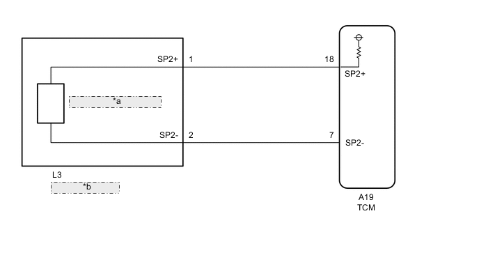
| *a | Output Speed Sensor SP2 |
| *b | Transmission Wire |
CAUTION / NOTICE / HINT
Note
Perform the universal trip to clear permanent DTCs Click here.
-
DATA LIST
Tech Tips
Using the GTS to read the Data List allows the values or states of switches, sensors, actuators and other items to be read without removing any parts. This non-intrusive inspection can be very useful because intermittent conditions or signals may be discovered before parts or wiring is disturbed. Reading the Data List information early in troubleshooting is one way to save diagnostic time.
Note
In the table below, the values listed under "Normal Condition" are reference values. Do not depend solely on these reference values when deciding whether a part is faulty or not.
-
Warm up the engine.
-
Turn the ignition switch OFF.
-
Connect the GTS to the DLC3.
-
Turn the ignition switch to ON.
-
Turn the GTS on.
-
Enter the following menus: Powertrain / ECT / Data List.
-
According to the display on the GTS, read the "Data List".
Item Measurement Item/
Range (display)
Normal Condition SPD (SP2) Output shaft speed/
Min.: 0 km/h (0 mph)
Max.: 255 km/h (158 mph)
Tech Tips
Vehicle stopped: 0 km/h (0 mph) (output shaft speed is equal to vehicle speed)
Tech Tips
-
SPD (SP2) is always 0 while driving:
Open or short in the sensor or circuit.
-
SPD (SP2) is always more than 0 and less than 300 rpm while driving the vehicle at 50 km/h (31 mph) or more:
Sensor trouble, improper installation, or intermittent connection trouble of the circuit.
-
-
PROCEDURE
-
INSPECT SPEED SENSOR INSTALLATION
-
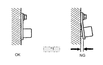
*1 Clearance Check the output speed sensor SP2 installation.
OK The installation bolt is tightened properly and there is no clearance between the sensor and transmission case.
NG 
SECURELY INSTALL SPEED SENSOR OR REPLACE SPEED SENSOR Click here
OK 
-
-
INSPECT OUTPUT SPEED SENSOR SP2
-
Disconnect the speed sensor connector.
-
Perform inspection of the output speed sensor SP2 Click here.
-
Connect the speed sensor connector.
NG
REPLACE OUTPUT SPEED SENSOR SP2
OK
-
-
CHECK HARNESS AND CONNECTOR (OUTPUT SPEED SENSOR SP2 - TCM)
-
Disconnect the A19 TCM connector.
-
Disconnect the L3 output speed sensor SP2 connector.
-
Measure the resistance according to the value(s) in the table below.
Standard resistance Tester Connection Condition Specified Condition L3-1(SP2+) - A19-18(SP2+) Always Below 1 Ω L3-2(SP2-) - A19-7(SP2-) Always Below 1 Ω A19-18(SP2+) - Body ground Always 10 kΩ or higher A19-7(SP2-) - Body ground Always 10 kΩ or higher -
Connect the A19 TCM connector.
-
Connect the L3 output speed sensor SP2 connector.
NG
REPAIR OR REPLACE HARNESS OR CONNECTOR
OK
-
-
REPLACE TCM
-
Replace the TCM Click here.
NEXT
PERFORM THE RESET MEMORY Click here
-