BODY STRUCTURE
-
CONSTRUCTION
-
Impact Absorbing Structure for Frontal Collision
-
A structure that ensures collision energy absorption efficiency, dissipates impact and minimizes cabin deformation during a frontal collision has been achieved.
-
A frame construction which effectively transmits the impact load to the vehicle body parts during a frontal collision is used.
-
Ultra high strength sheet steel (Tensile Strength: 590 MPa class) rocker panel outer (*1 in illustration) and rocker panel reinforcement No. 1(*2 in illustration) are provided to help reduce the deformation of the rocker during a frontal collision.
-
Ultra high strength sheet steel (Tensile Strength: 590 MPa class) front body pillar reinforcement upper (*3 in illustration) and roof side rail outer (*4 in illustration) are used. The deformation of the front body pillars has been reduced during a frontal collision by overlapping the points at where the load concentrates most on the front body pillars during a frontal collision to provide further reinforcement.
-
The impact load is transmitted to the non-impacted side during an offset frontal collision to help reduce the vehicle deformation amount by providing a front bumper reinforcement No. 5 (*6 in illustration) within the cross section of the front bumper reinforcement sub-assembly (*7 in illustration).
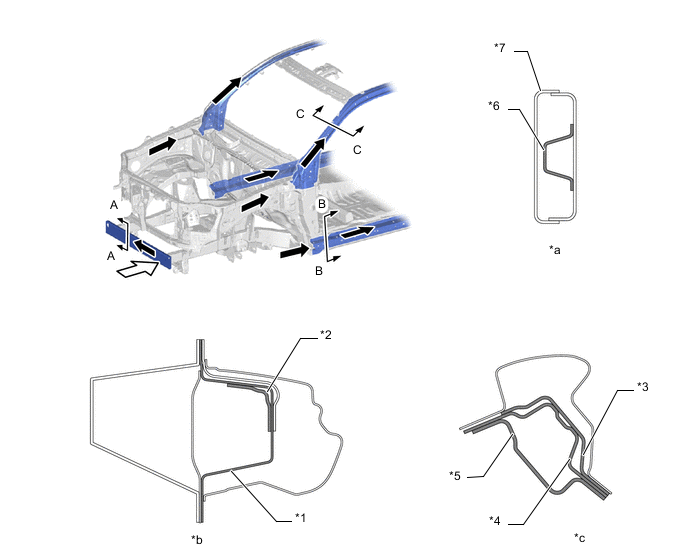
*1 Rocker Panel Outer *2 Rocker Panel Reinforcement No. 1 *3 Front Body Pillar Reinforcement Upper *4 Roof Side Rail Outer *5 Front Body Pillar Inner *6 Front Bumper Reinforcement No. 5 *7 Front Bumper Reinforcement Sub-assembly - - *a A - A Cross Section *b B - B Cross Section *c C - C Cross Section - - 
Front Impact Energy 
Dissipate -
The frame sub-assembly deformation pattern during a frontal collision is controlled to move the suspension tower, dash panel and pedals away from the passengers, reducing their level of injury.
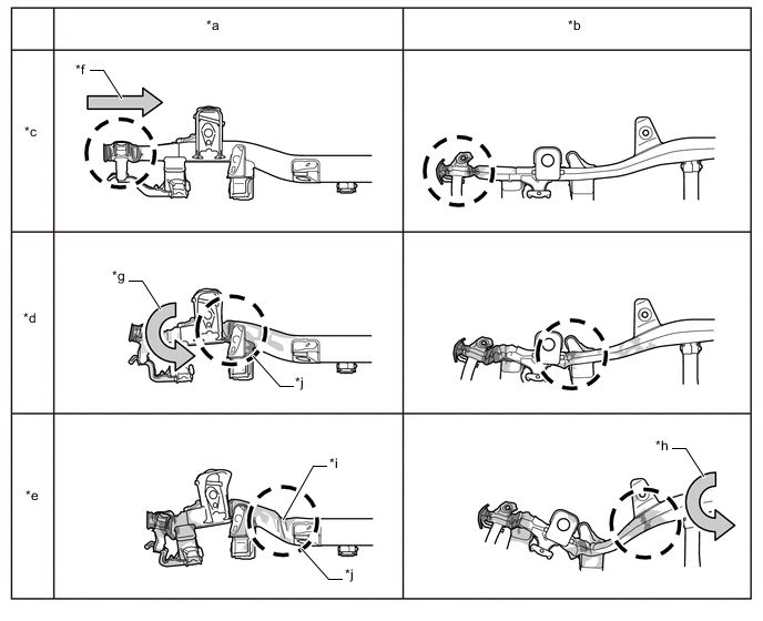
*a Side View *b Plane View *c Step 1: Extension Bucking *d Step 2: Side Rail Collapsing Below Suspension Tower *e Step 3: Side Rail Collapsing *f Bucking *g Longitudinal Collapsing *h Lateral Collapsing *i Kick Region *j Deformation of the side-rail "kick" portionis controlled to reduce the deformation amount of the suspension tower, dash panel and pedals, reducing impact load delivered to the passengers during a collision.
-
-
-
Impact Absorbing Structure for Side Collision
-
A structure that ensures collision energy absorption efficiency, dissipates impact and minimizes cabin deformation during a side collision has been achieved.
-
A frame construction which effectively disperses the impact load during a side collision is used.
-
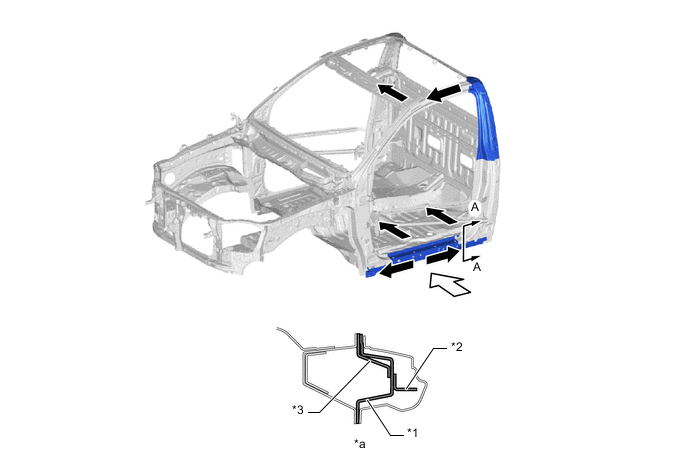
On double cab models, ultra high strength sheet steel (Tensile Strength: 590 MPa class) rocker panel outer (*1 in illustration) is provided to help reduce the deformation of the rocker during a side collision.
-
On double cab models, during the initial operation of the airbags, the rocker extension outer (*3 in illustration) and rocker panel reinforcement No. 4 (*2 in illustration) transmits the impact load to the floor to help reduce vehicle body deformation during a side collision.
-
On double cab models, the center body pillar is provided with an ultra high strength sheet steel (Tensile Strength: 590 MPa class) center body pillar reinforcement upper (*4 in illustration) to help reduce the deformation of the center body pillar during a side collision.
Figure 1. Double Cab
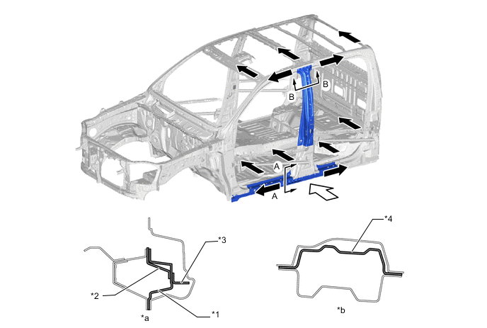
*1 Rocker Panel Outer *2 Rocker Panel Reinforcement No. 4 *3 Rocker Extension Outer *4 Center Body Pillar Reinforcement Upper *a A - A Cross Section *b B - B Cross Section Side Impact Energy Dissipate -
On smart cab models, ultra high strength sheet steel (Tensile Strength: 590 MPa class) rocker panel outer (*1 in illustration) and ultra high strength sheet steel (Tensile Strength:590 MPa class) access panel Inside panel reinforcement (*4 in illustration) are provided to help reduce the deformation of the rocker during a side collision.
-
On smart cab models, during the initial operation of the airbags, the rocker extension outer (*2 in illustration) and rocker panel reinforcement No. 4 (*3 in illustration) transmits the impact load to the floor to help reduce vehicle body deformation during a side collision.
Figure 2. Smart Cab
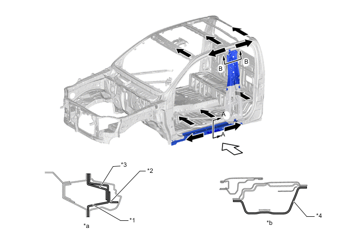
*1 Rocker Panel Outer *2 Rocker Extension Outer *3 Rocker Panel Reinforcement No. 4 *4 Access Panel Inside Panel Reinforcement *a A - A Cross Section *B B - B Cross Section Side Impact Energy Dissipate -
On single cab models, ultra high strength sheet steel (Tensile Strength: 590 MPa class) rocker panel outer (*1 in illustration) is provided to help reduce the deformation of the rocker during a side collision.
-
On single cab models, during the initial operation of the airbags, the rocker extension outer (*2 in illustration) and rocker panel reinforcement No. 4 (*3 in illustration) transmits the impact load to the floor to help reduce vehicle body deformation during a side collision.
Figure 3. Single Cab
*1 Rocker Panel Outer *2 Rocker Extension Outer *3 Rocker Panel Reinforcement No. 4 - - *a A - A Cross Section - - Side Impact Energy Dissipate
-
-
-
Reduction Pedestrian Head Injury
-
The following shape is used for around the front body, thus maintaining necessary rigidity and aiming for a reduction of impact against a pedestrian in a collision with a pedestrian.
-
The hood sub-assembly (*1 in illustration) uses a structure that places a sufficient space between the hood panel (*2 in illustration) and hood panel inner (*3 in illustration) to ensure an impact absorption stroke (*b in illustration) in order to reduce the impact to the head of a pedestrian during a collision.
Figure 4. Hood Sub-assembly (The illustration shows an example)
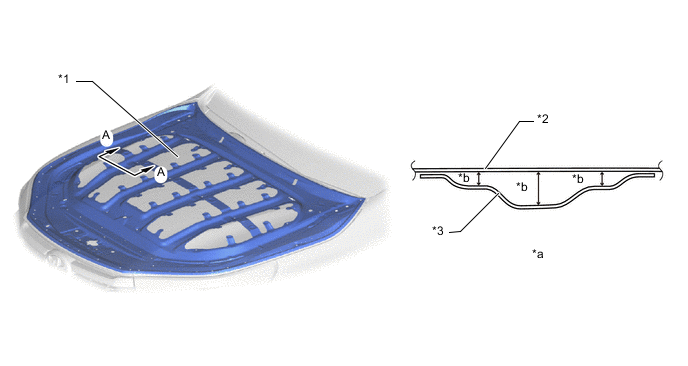
*1 Hood Sub-assembly *2 Hood Panel *3 Hood Panel Inner - - *a A - A Cross Section *b Impact Absorption Stroke -
The hood sub-assembly (*1 in illustration) uses a structure that places a sufficient space between the hood panel (*4 in illustration) and engine compartment parts (*5 in illustration) to ensure an impact absorption stroke (*b in illustration) in order to reduce the impact to the head of a pedestrian during a collision.
-
Deformation points (*c in illustration) are placed on the hood lock hook reinforcement No. 2 (*3 in illustration) to create an easily collapsible structure that can absorb the impact load effectively when a pedestrian collides with the hood lock area in order to reduce the impact to the head of a pedestrian.
Figure 5. Hood Sub-assembly (The illustration shows an example)
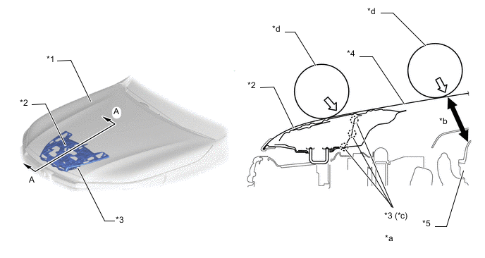
*1 Hood Sub-assembly *2 Hood Panel Reinforcement *3 Hood Lock Hook Reinforcement No. 2 *4 Hood Panel *5 Engine Compartment Parts - - *a A - A Cross Section *b Impact Absorption Stroke *c Deformation Point *d Head Form -
The cowl top panel inner (*1 in illustration) uses a crushable structure that has deformation points (*b in illustration) to improve the rate of energy absorption from the estimated collision direction when a pedestrian collides with the windshield glass (*2 in illustration) to reduce the impact to the pedestrian whose head, etc., struck the area.
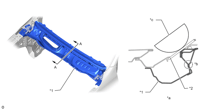
*1 Cowl Top Panel Inner *2 Windshield Glass *a A - A Cross Section *b Deformation Point *c Head Form - - -
An impact absorption brackets (fender apron reinforce plate: *1 in illustration and front fender apron reinforcement RR: *2 in illustration) are provided around the front fender apron sub-assembly (*3 in illustration) to absorb impact load during a collision and collapse, forming a structure which reduces the impact to the pedestrian whose head, etc., struck the fender.
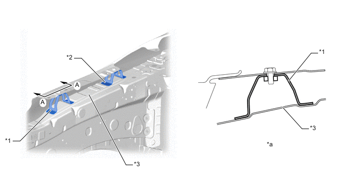
*1 Fender Apron Reinforce Plate *2 Front Fender Apron Reinforcement RR *3 Front Fender Apron Sub-assembly - - *a A - A Cross Section - -
-
-
-