COMPRESSOR (for 1GR-FE) INSTALLATION
-
ADJUST COMPRESSOR OIL
-
When replacing the compressor with a new one after gradually releasing the refrigerant gas from the service valve, drain the following amount of oil from the new compressor before installation.
Standard (Oil capacity inside new compressor: 80 + 15 cc (2.7 + 0.5 fl. oz.) - (Remaining oil amount in the removed compressor) = (Oil amount to be removed when replacing) Note
-
When checking the compressor oil level, follow the A/C system's precautions.
-
Since compressor oil remains in the pipes of the vehicle, if a new compressor is installed without removing some oil inside, the oil amount becomes excessive. Excessive oil prevents heat exchange in the refrigerant cycle and causes refrigerant failure.
-
Be sure to use ND-OIL 8 for compressor oil.
-
-
-
INSTALL COOLER COMPRESSOR ASSEMBLY
-
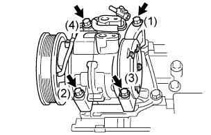
Install the compressor and cooler bracket with the 4 bolts and tighten the bolts in the order shown in the illustration.
- Torque:
- 25 N*m { 250 kgf*cm, 18 ft.*lbf }
-
Connect the connector and attach the clamp.
-
-
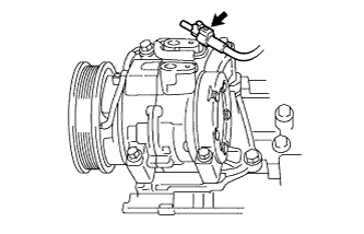
INSTALL NO. 1 COOLER REFRIGERANT DISCHARGE HOSE
-
Remove the vinyl tape attached to the No. 1 cooler refrigerant discharge hose.
-
Sufficiently apply compressor oil to a new O-ring and the fitting surface of the compressor.
Compressor oil ND-OIL 8 or equivalent -
Install the O-ring to the No. 1 cooler refrigerant discharge hose.
-
Connect the No. 1 cooler refrigerant discharge hose with the bolt.
- Torque:
- 9.8 N*m { 100 kgf*cm, 87 in.*lbf }
-
-
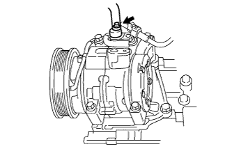
INSTALL SUCTION HOSE SUB-ASSEMBLY
-
Remove the vinyl tape attached to the suction hose sub-assembly.
-
Sufficiently apply compressor oil to a new O-ring and the fitting surface of the compressor.
Compressor oil ND-OIL 8 or equivalent -
Install the O-ring on the suction hose sub-assembly.
-
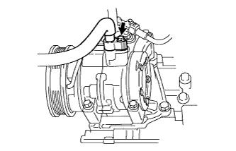
Connect the suction hose sub-assembly with the bolt.
- Torque:
- 9.8 N*m { 100 kgf*cm, 87 in.*lbf }
-
-
INSTALL FAN AND GENERATOR V BELT
-
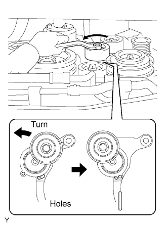
While turning the belt tensioner counterclockwise, align its holes, and then insert a bar of 6 mm (0.24 in.) into the holes to fix the belt tensioner.
-
Install the V-ribbed belt.
-
While turning the belt tensioner counterclockwise, remove the bar.
-
If it is hard to install the V-ribbed belt, perform the following procedure.
-
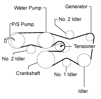
Put the V-ribbed belt on everything except the P/S pump as shown in the illustration.
-
While releasing the belt tension by turning the belt tensioner counterclockwise, put the V-ribbed belt on the P/S pump.
-
-
-
CHARGE REFRIGERANT
- SST
- 09985-20010 ( 09985-02130, 09985-02150, 09985-02090, 09985-02110, 09985-02010, 09985-02050, 09985-02060, 09985-02070 )
-
Perform vacuum purging using a vacuum pump.
-
Charge refrigerant HFC-134a (R134a).
Standard 450 +- 30 g (15.87 +- 1.05 oz.) 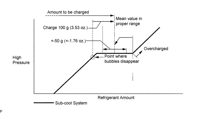
Note
-
Do not operate the cooler compressor before charging refrigerant as the cooler compressor will not work properly without any refrigerant, and will overheat.
-
Approximately 100 g (3.53 oz.) of refrigerant may need to be charged after bubbles disappear. The refrigerant amount should be checked by quantity, and not with the sight glass.
-
-
WARM UP ENGINE
-
Warm up the engine at less than 1,850 rpm for 2 minutes or more after charging refrigerant.
Note
After removing and installing the cooler refrigerant lines (with the compressor), be sure to warm up the compressor when turning the A/C switch ON. This is done to prevent damage to the compressor.
-
-
CHECK FOR LEAKAGE OF REFRIGERANT
-
After recharging the refrigerant gas, prepare the vehicle for a refrigerant gas leakage check by making sure the following conditions are met.
-
The ignition switch is OFF.
-
The vehicle is in a place with good air ventilation and without any volatile gases, such as evaporated gasoline or exhaust gas. The detector is very sensitive to volatile gases. If volatile gases are unavoidable, the vehicle must be lifted up.
-
Some refrigerant is remaining in the refrigerant system.
-
The compressor is OFF and its pressure is approximately 392 to 588 kPa (4 to 6 kgf/cm2).
-
-
Check for refrigerant gas leakage from the refrigerant line.
-
After the blower motor stops, wait at least 15 minutes.
-
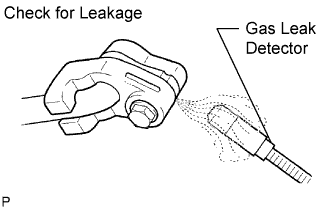
Using a gas leak detector, check that gas is not leaking from the refrigerant line. If leakage is found, tighten parts or replace damaged parts as necessary to stop the leak.
-
-
Check for refrigerant gas leakage from the cooling unit.
-
Hold the gas leak detector so that the sensor is under the drain hose, as shown in the illustration.
-
Check that gas is not leaking from the drain hose. If leakage is found, tighten parts or replace damaged parts as necessary to stop the leak.
-
-
Check for refrigerant gas leakage from the cooling unit.
-
Remove the blower motor control from the unit. Insert the gas leak detector's sensor into the unit.
-
Check that gas is not leaking from the unit. If leakage is found, tighten parts or replace damaged parts as necessary to stop the leak.
-
-
Check for refrigerant gas leakage from the pressure switch.
-
Disconnect the pressure switch connector and wait approximately 20 minutes.
-
Using a gas leak detector, check that gas is not leaking from the pressure switch. If leakage is found, tighten parts or replace damaged parts as necessary to stop the leak.
-
-
Repeat all steps above 2 to 3 times.
-