BODY STRUCTURE
-
CONSTRUCTION
-
Anti-corrosion Sheet Steel
-
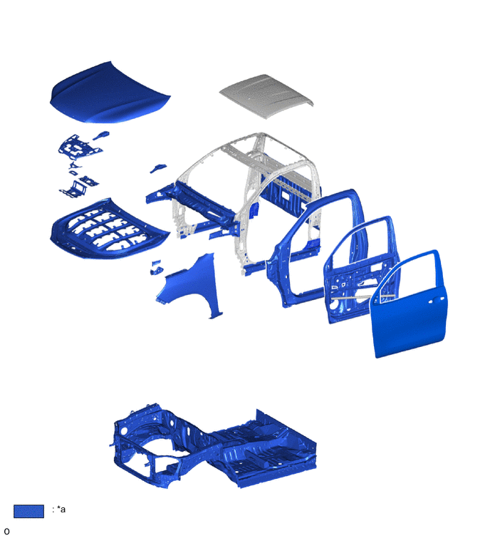
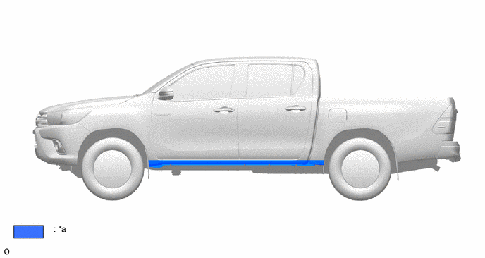
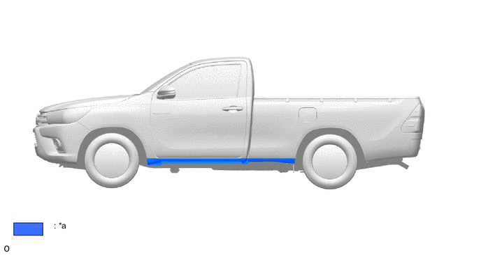
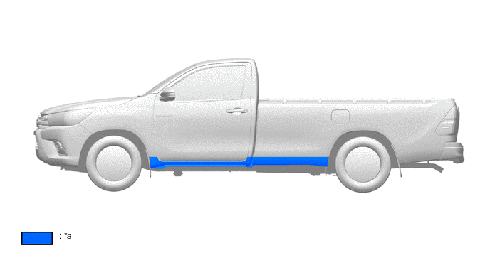
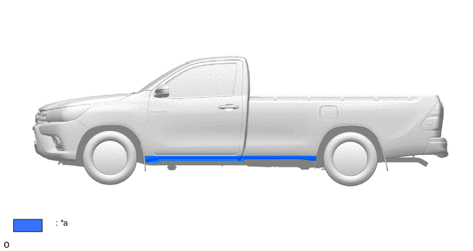
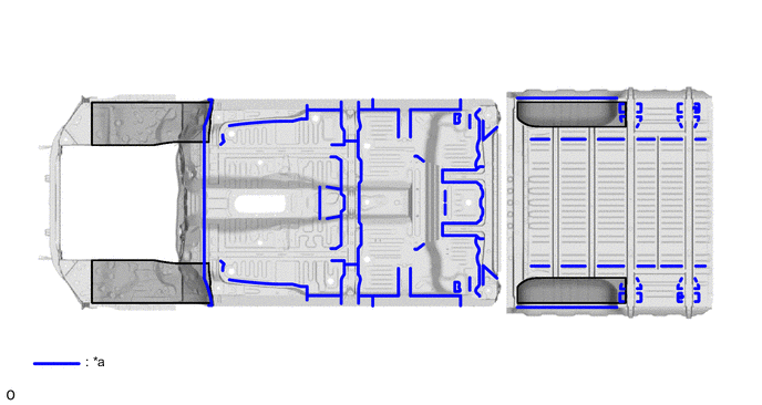
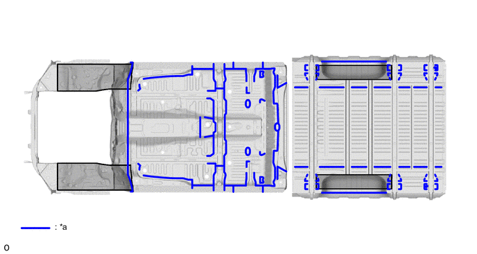
Anti-corrosion sheet steel is used as in the following illustration:
Figure 1. Double Cab (Body)
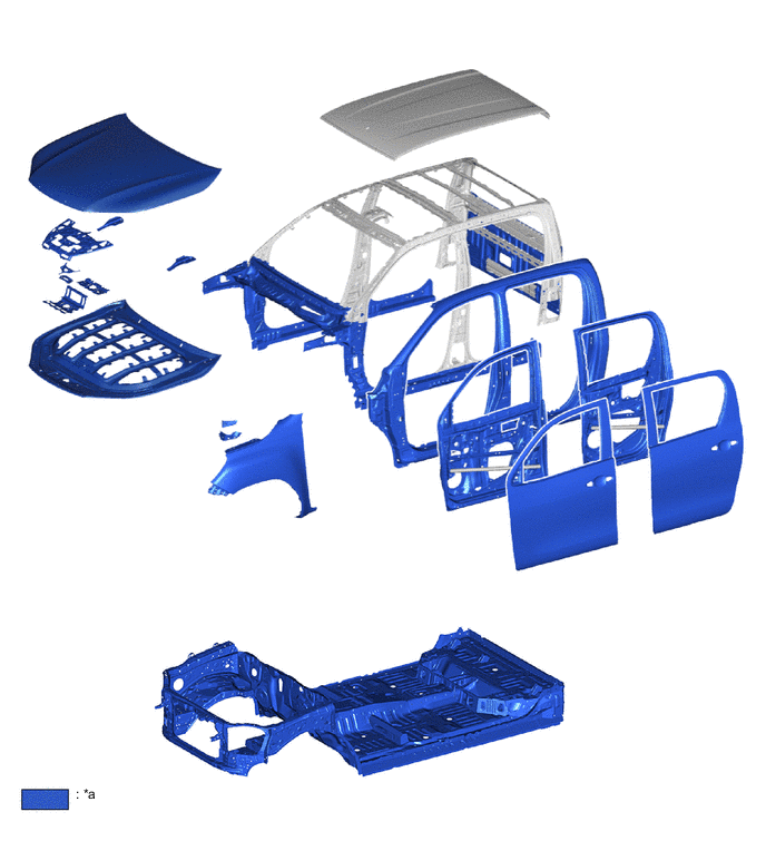
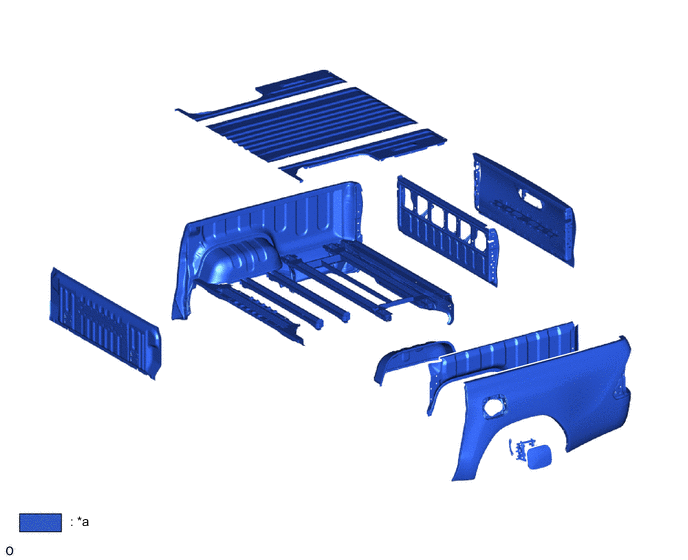
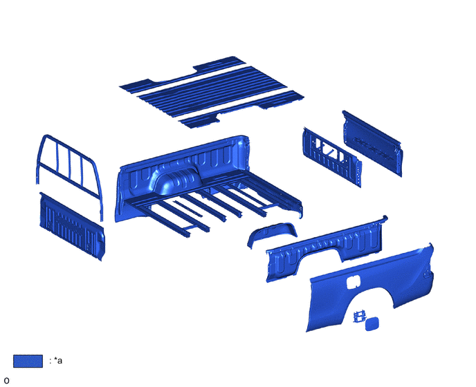
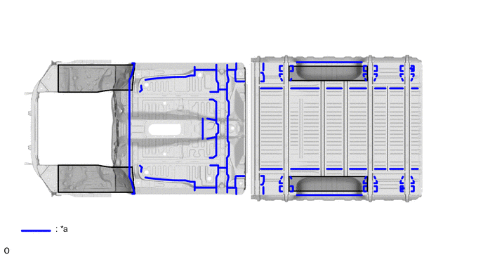
*a Anti-corrosion Sheet Steel - - Figure 2. Double Cab (Deck)
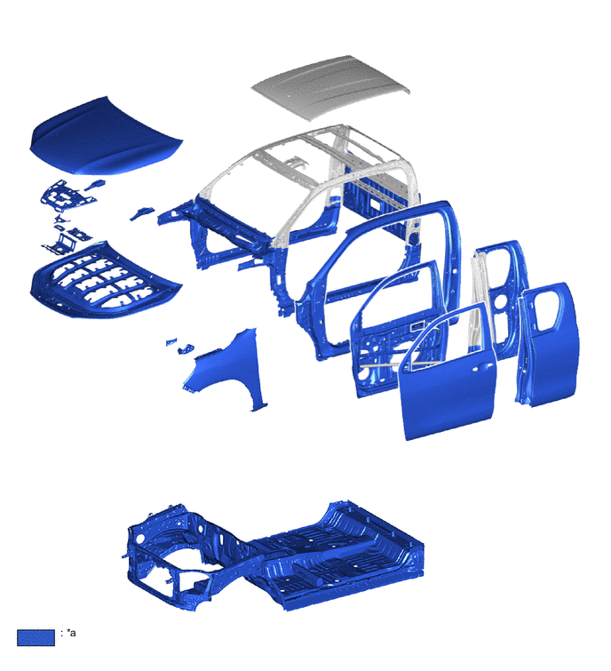
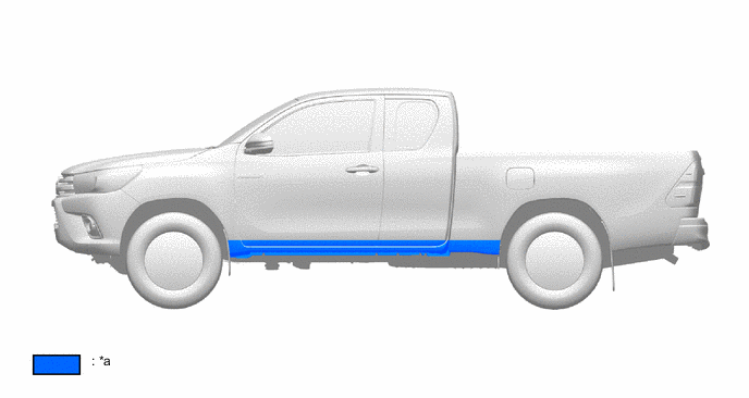
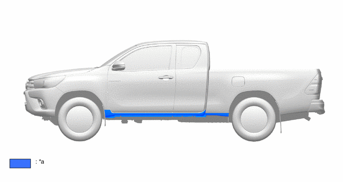
*a Anti-corrosion Sheet Steel - - Figure 3. Smart Cab (Body)
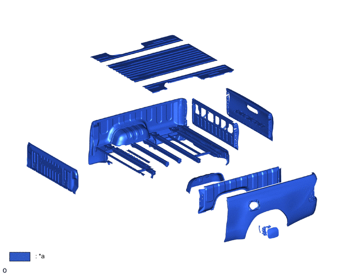
*a Anti-corrosion Sheet Steel - - Figure 4. Smart Cab (Deck)
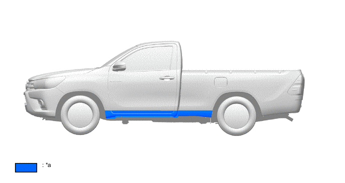
*a Anti-corrosion Sheet Steel - - Figure 5. Single Cab (Body)
*a Anti-corrosion Sheet Steel - - Figure 6. Single Cab (Deck)
*a Anti-corrosion Sheet Steel - -
-
-
Anti-chipping Application and Rust-resistant Performance
-
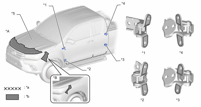
Wax is applied to the edge of the door lower portion, door hinge, fuel filler opening lid assembly, and the hemmed portions of the hood sub-assembly each door panels and deck to improve rust-resistant performance.
-
Soft anti-chipping primer and Polyvinyl Chloride (PVC) anti-chipping coating are applied to various parts of the body to help prevent rust.
Figure 7. Double Cab (Cab: The illustration shows an example)
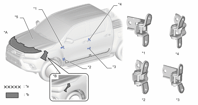
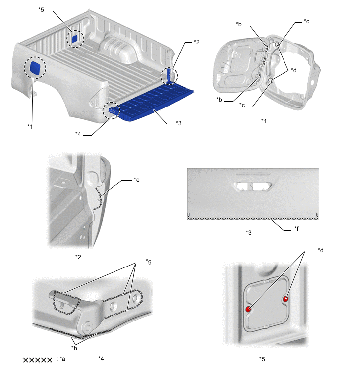
*A Wide Body Model *B Narrow Body Model *1 Front Door Hinge Assembly Upper *2 Front Door Hinge Assembly Lower *3 Rear Door Hinge Assembly Lower *4 Rear Door Hinge Assembly Upper *5 Hood Sub-assembly - - *a Wax *b Soft Anti-chipping Primer Application Range (Models for Europe and Iraq) Figure 8. Double Cab (Deck: The illustration shows an example)
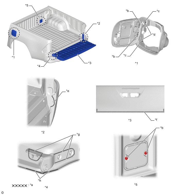
*1 Fuel Filler Opening Lid Assembly *2 Rear End Post *3 Rear Body Tail Gate Assembly *4 Tail Gate Hinge *5 Header Board Plate (ED Hole) - - *a Wax *b Hinge Curling Portion *c Edge Area *d Head of Rivet *e Portion of No Indication To Applied Body Sealer *f Additional Wax Application Inside of Tailgate *g Fitting Portion of Tail Gate Hinge *h Tail Gate Hemming Portion Figure 9. Smart Cab (Cab: The illustration shows an example)
*A Wide Body Model *B Narrow Body Model *1 Front Door Hinge Assembly Upper *2 Front Door Hinge Assembly Lower *3 Access Panel Hinge Assembly Lower *4 Access Panel Hinge Assembly Upper *5 Hood Sub-assembly - - *a Wax *b Soft Anti-chipping Primer Application Range (Models for Europe) Figure 10. Smart Cab (Deck: The illustration shows an example)
*1 Fuel Filler Opening Lid Assembly *2 Rear End Post *3 Rear Body Tail Gate Assembly *4 Tail Gate Hinge *5 Header Board Plate (ED Hole) - - *a Wax *b Hinge Curling Portion *c Edge Area *d Head of Rivet *e Portion of No Indication To Applied Body Sealer *f Additional Wax Application Inside of Tailgate *g Fitting Portion of Tail Gate Hinge *h Tail Gate Hemming Portion Figure 11. Single Cab (Cab: The illustration shows an example)
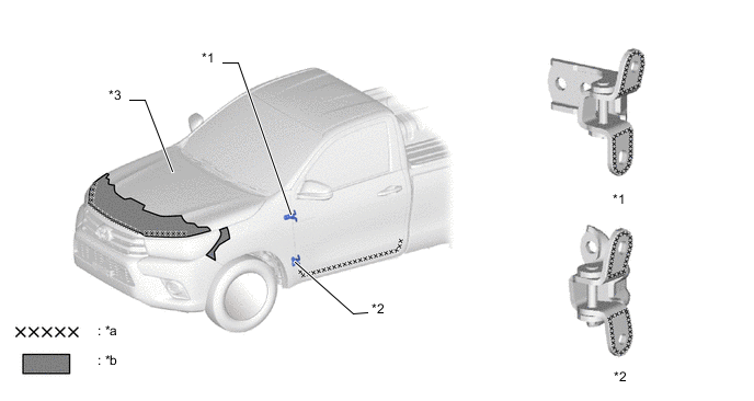
*1 Front Door Hinge Assembly Upper *2 Front Door Hinge Assembly Lower *3 Hood Sub-assembly - - *a Wax *b Soft Anti-chipping Primer Application Range (Models for Iraq) Figure 12. Single Cab (Deck: The illustration shows an example)
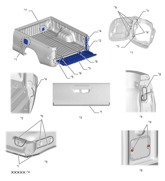
*1 Fuel Filler Opening Lid Assembly *2 Rear End Post *3 Rear Body Tail Gate Assembly *4 Hook Tail Gate Latch *5 Tail Gate Hinge *6 Tail Gate Heavy Duty Hinge *7 Header Board Plate (ED Hole) - - *a Wax *b Hinge Curling Portion *c Edge Area *d Head of Rivet *e Portion of No Indication To Applied Body Sealer *f Additional Wax Application Inside of Tailgate *g Fitting Portion of Tail Gate Latch *h Fitting Portion of Tail Gate Hinge *i Tail Gate Hemming Portion - - Figure 13. Double Cab Type1 (The illustration shows an example)

*a Polyvinyl Chloride (PVC) Anti Chipping Coating - - Figure 14. Double Cab Type2 (The illustration shows an example)
*a Polyvinyl Chloride (PVC) Anti Chipping Coating - - Figure 15. Smart Cab Type1 (The illustration shows an example)
*a Polyvinyl Chloride (PVC) Anti Chipping Coating - - Figure 16. Smart Cab Type2 (The illustration shows an example)
*a Polyvinyl Chloride (PVC) Anti Chipping Coating - - Figure 17. Single Cab Type1 (Short Wheel Base: The illustration shows an example)
*a Polyvinyl Chloride (PVC) Anti Chipping Coating - - Figure 18. Single Cab Type2 (Short Wheel Base: The illustration shows an example)
*a Polyvinyl Chloride (PVC) Anti Chipping Coating - - Figure 19. Single Cab Type1 (Long Wheel Base: The illustration shows an example)
*a Polyvinyl Chloride (PVC) Anti Chipping Coating - - Figure 20. Single Cab Type2 (Long Wheel Base: The illustration shows an example)
*a Polyvinyl Chloride (PVC) Anti Chipping Coating - - -
Under coating is applied to the wheel housings, and other parts that are located where they are susceptible to stone chipping damage, improving the rust-resistance of these areas.
Figure 21. Double Cab
*a Edge Seal - - 
Under Coating Area - - Figure 22. Smart Cab
*a Edge Seal - - Under Coating Area - - Figure 23. Single Cab
*a Edge Seal - - Under Coating Area - -
-
-