WIRELESS DOOR LOCK CONTROL SYSTEM TERMINALS OF ECU
-
CHECK INSTRUMENT PANEL JUNCTION BLOCK ASSEMBLY AND MAIN BODY ECU (MULTIPLEX NETWORK BODY ECU)
-
Disconnect the MB and L190*1 main body ECU (multiplex network body ECU) connectors.
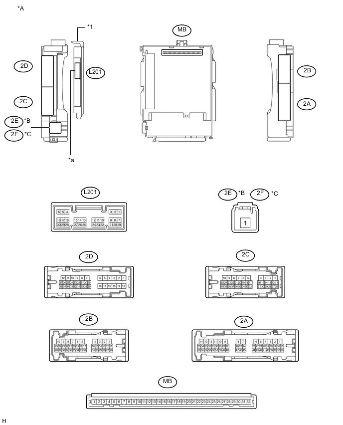
Text in Illustration *A Main Body ECU (Multiplex Network Body ECU) with 1 connector *B for LHD *C for RHD - - *1 Main Body ECU (Multiplex Network Body ECU) - - *a 1 connector - - 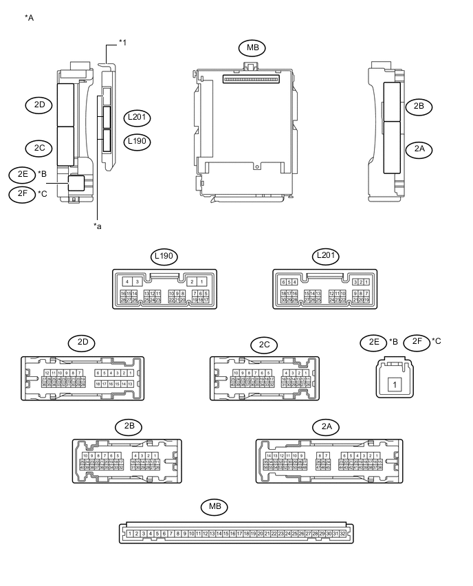
Text in Illustration *A Main Body ECU (Multiplex Network Body ECU) with 3 connectors *B for LHD *C for RHD - - *1 Main Body ECU (Multiplex Network Body ECU) - - *a 3 connectors - - -
Measure the voltage and resistance according to the value(s) in the table below.
Tech Tips
Measure the values on the wire harness side with the connectors disconnected.
Tester Connection Wiring Color Terminal Description Condition Specified Condition MB-11 (GND1) - Body ground - Ground Always Below 1 Ω L190-3 (GND2) - Body ground*1 W-B - Body ground Ground Always Below 1 Ω MB-30 (BECU) - Body ground - Auxiliary battery power supply Power switch off 11 to 14 V MB-29 (ACC) - Body ground - ACC power supply Power switch on (ACC) 11 to 14 V MB-29 (ACC) - Body ground - ACC power supply Power switch off Below 1 V MB-32 (IG) - Body ground - Power switch power supply Power switch on (IG) 11 to 14 V MB-32 (IG) - Body ground - Power switch power supply Power switch off Below 1 V If the result is not as specified, there may be a malfunction in the wire harness.
-
Reconnect the MB and L190*1 main body ECU (multiplex network body ECU) connectors.
-
Measure the voltage according to the value(s) in the table below.
Tester Connection Wiring Color Terminal Description Condition Specified Condition 2B-1 (ACT-) - Body ground B - Body ground Door lock motor unlock drive output Door control switch (multiplex network master switch) or driver door key cylinder off Below 1 V 2B-1 (ACT-) - Body ground B - Body ground Door lock motor unlock drive output Door control switch (multiplex network master switch) or driver door key cylinder unlocked 11 to 14 V 2B-3 (ACT-) - Body ground LG - Body ground Door lock motor unlock drive output Door control switch (multiplex network master switch) or driver door key cylinder off Below 1 V 2B-3 (ACT-) - Body ground LG - Body ground Door lock motor unlock drive output Door control switch (multiplex network master switch) or driver door key cylinder unlocked 11 to 14 V 2D-11 (ACT-) - Body ground V - Body ground Door lock motor unlock drive output Door control switch (multiplex network master switch) or driver door key cylinder off Below 1 V 2D-11 (ACT-) - Body ground V - Body ground Door lock motor unlock drive output Door control switch (multiplex network master switch) or driver door key cylinder unlocked 11 to 14 V 2B-8 (ACT+) - Body ground L - Body ground Door lock motor lock drive output Door control switch (multiplex network master switch) or driver door key cylinder off Below 1 V 2B-8 (ACT+) - Body ground L - Body ground Door lock motor lock drive output Door control switch (multiplex network master switch) or driver door key cylinder locked 11 to 14 V 2B-9 (ACT+) - Body ground R - Body ground Door lock motor lock drive output Door control switch (multiplex network master switch) or driver door key cylinder off Below 1 V 2B-9 (ACT+) - Body ground R - Body ground Door lock motor lock drive output Door control switch (multiplex network master switch) or driver door key cylinder locked 11 to 14 V 2B-10 (ACT+) - Body ground P - Body ground Door lock motor lock drive output Door control switch (multiplex network master switch) or driver door key cylinder off Below 1 V 2B-10 (ACT+) - Body ground P - Body ground Door lock motor lock drive output Door control switch (multiplex network master switch) or driver door key cylinder locked 11 to 14 V 2D-12 (ACT+) - Body ground L - Body ground Door lock motor lock drive output Door control switch (multiplex network master switch) or driver door key cylinder off Below 1 V 2D-12 (ACT+) - Body ground L - Body ground Door lock motor lock drive output Door control switch (multiplex network master switch) or driver door key cylinder locked 11 to 14 V 2D-35 (FLCY) - Body ground Y - Body ground*2
V - Body ground*3
Front door LH courtesy light switch input Front door LH open Below 1 V 2D-35 (FLCY) - Body ground Y - Body ground*2
V - Body ground*3
Front door LH courtesy light switch input Front door LH closed 11 to 14 V 2D-36 (FRCY) - Body ground BR - Body ground*2
V - Body ground*3
Front door RH courtesy light switch input Front door RH open Below 1 V 2D-36 (FRCY) - Body ground BR - Body ground*2
V - Body ground*3
Front door RH courtesy light switch input Front door RH closed 11 to 14 V L201-6 (LRCY) - Body ground G - Body ground Rear door courtesy light switch input Rear door LH or RH open Below 1 V L201-6 (LRCY) - Body ground G - Body ground Rear door courtesy light switch input Rear door LH and RH closed Pulse generation L201-7 (LSFL) - Body ground GR - Body ground Front door LH unlock detection switch input Front door LH unlocked Below 1 V L201-7 (LSFL) - Body ground GR - Body ground Front door LH unlock detection switch input Power switch off, all doors closed and front door LH locked Pulse generation L201-18 (LSFR) - Body ground LG - Body ground Front door RH unlock detection switch input Front door RH unlocked Below 1 V L201-18 (LSFR) - Body ground LG - Body ground Front door RH unlock detection switch input Power switch off, all doors closed and front door RH locked Pulse generation 2B-29 (LSR) - Body ground GR - Body ground Rear door RH unlock detection switch input Rear door RH or LH unlocked Below 1 V 2B-29 (LSR) - Body ground GR - Body ground Rear door RH unlock detection switch input Power switch off, all doors closed, rear door RH and LH locked Pulse generation 2D-25 (LSR) - Body ground GR - Body ground Rear door LH unlock detection switch input Rear door LH or RH unlocked Below 1 V 2D-25 (LSR) - Body ground GR - Body ground Rear door LH unlock detection switch input Power switch off, all doors closed, rear door LH and RH locked Pulse generation 2C-23 (BZR) - Body ground R - Body ground Wireless door lock buzzer signal Wireless door lock buzzer off Below 1 V 2C-23 (BZR) - Body ground R - Body ground Wireless door lock buzzer signal Wireless door lock buzzer on 11 to 14 V
-
*1: Main body ECU (Multiplex Network Body ECU) with 3 connectors
-
*2: for LHD
-
*3: for RHD
If the result is not as specified, the main body ECU (multiplex network body ECU) or instrument panel junction block assembly may have a malfunction.
-
-
-
CHECK CERTIFICATION ECU (SMART KEY ECU ASSEMBLY)
-
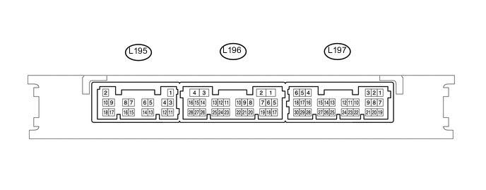
Disconnect the L195 certification ECU (smart key ECU assembly) connector.
-
Measure the resistance and voltage according to the value(s) in the table below.
Terminal No. (Symbol) Wiring Color Terminal Description Condition Specified Condition L195-11 (E) - Body ground W-B - Body ground Ground Always Below 1 Ω L195-2 (+B) - L195-11 (E) B - W-B Auxiliary battery power supply Power switch off 11 to 14 V
-
If the result is not as specified, there may be a malfunction in the wire harness.
-
-
Reconnect the L195 certification ECU (smart key ECU assembly) connector.
-
Measure the voltage according to the value(s) in the table below.
Terminal No. (Symbol) Wiring Color Terminal Description Condition Specified Condition L197-5 (IG) - L195-11 (E) BE - W-B IG power supply Power switch on (IG) 11 to 14 V L196-17 (RDAM) - L195-11 (E) GR - W-B*1
Y - W-B*2
RF signal input circuit Proceed:
-
All doors closed
-
All doors locked
-
Electrical key transmitter sub-assembly not inside vehicle
-
Electrical key transmitter sub-assembly brought outside detection area but kept inside wireless function operational area
-
Lock or unlock switch of electrical key transmitter sub-assembly not pressed → pressed
11 to 14 V pulse generation at regular intervals → pulse generation L196-6 (CSEL) - L195-11 (E) V - W-B*1
SB - W-B*2
Communication channel switching circuit Proceed:
-
Power switch off
-
All doors closed
No pulse generation → pulse generation L196-5 (RCO) - L195-11 (E) LG - W-B Wireless tuner power supply output circuit Proceed:
-
Power switch off
-
Electrical key transmitter sub-assembly brought outside detection area but kept inside wireless function operational area
-
Lock or unlock switch of electrical key transmitter sub-assembly not pressed → pressed
Below 1 V → 4.5 to 5.5 V
-
*1: for 12 Pin Type
-
*2: for 5 Pin Type
-
If the result is not as specified, the certification ECU (smart key ECU assembly) may have a malfunction.
-
-