WIPER AND WASHER SYSTEM(w/o Rain Sensor) Headlight Cleaner Switch Circuit
| DTC Code | DTC Name |
|---|---|
| Headlight Cleaner Switch Circuit |
DESCRIPTION
This circuit detects the conditions (on or off) of the headlight cleaner switch assembly.
WIRING DIAGRAM
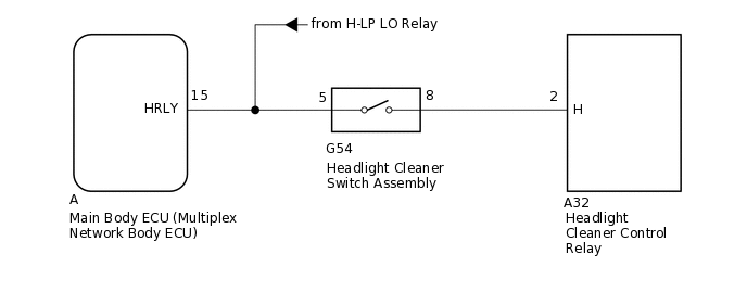
CAUTION / NOTICE / HINT
First check that the low beam headlights operate normally.
PROCEDURE
INSPECT HEADLIGHT CLEANER SWITCH ASSEMBLY
Remove the headlight cleaner switch assembly.
Inspect the headlight cleaner switch assembly.
Result
Proceed to
OK
NG
CHECK HARNESS AND CONNECTOR (HEADLIGHT CLEANER SWITCH ASSEMBLY - HEADLIGHT CLEANER CONTROL RELAY AND MAIN BODY ECU)
Disconnect the G54 headlight cleaner switch assembly connector.
Disconnect the A32 headlight cleaner control relay connector.
Remove the main body ECU (multiplex network body ECU).
Measure the resistance according to the value(s) in the table below.
Standard Resistance
Tester Connection
Condition
Specified Condition
G54-8 - A32-2 (H)
Always
Below 1 Ω
G54-8 or A32-2 (H) - Body ground
Always
10 kΩ or higher
Measure the voltage according to the value(s) in the table below.
Standard Voltage
Tester Connection
Condition
Specified Condition
G54-5 or A-15 (HRLY) - Body ground
Always
11 to 14 V
Result
Proceed to
OK
NG
NG REPAIR OR REPLACE HARNESS OR CONNECTOR