FRONT DRIVE SHAFT ASSEMBLY(for 1ZR-FAE, 2ZR-FAE) REASSEMBLY
CAUTION / NOTICE / HINT
When using a vise, place aluminum plates between the part and vise.
When using a vise, do not overtighten it.
PROCEDURE
INSTALL FRONT DRIVE SHAFT DUST COVER LH
-
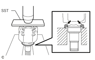
Using SST and a press, press on a new drive shaft dust cover.
09527-10011
Note:The dust cover should be installed completely.
Be careful not to damage the dust cover.
-
INSTALL FRONT DRIVE SHAFT DUST COVER RH
Tip:Use the same procedures described for the LH side.
INSTALL FRONT AXLE OUTBOARD JOINT BOOT
 Tip:
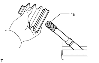
Tip:Before installing the boot, wrap the spline of the drive shaft with protective tape to prevent the boot from being damaged.
Table 1. Text in Illustration *a
Protective Tape
Install new parts to the outboard joint shaft in the following order.
No. 2 outboard joint boot clamp LH
Outboard joint boot
Outboard joint boot clamp LH
Pack the outboard joint shaft and boot with grease from the boot kit.
Standard Grease Capacity
Engine Type
Transaxle Type
Grease Capacity
1ZR-FAE
Manual transaxle
120 to 130 g (4.24 to 4.58 oz.)
2ZR-FAE
Continuously variable transaxle
Manual transaxle
149.5 to 159.5 g (5.28 to 5.62 oz.)
INSTALL FRONT NO. 2 AXLE OUTBOARD JOINT BOOT CLAMP LH
Secure the No. 2 outboard joint boot clamp to the boot.
-
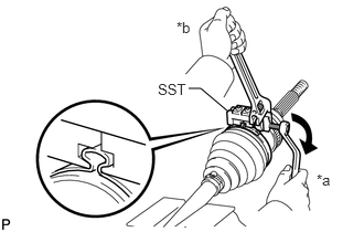
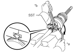
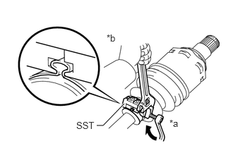
Place SST onto the No. 2 outboard joint boot clamp.
09521-24010
Table 2. Text in Illustration *a
Turn
*b
Hold
Tighten SST so that the No. 2 outboard joint boot clamp is pinched.
Note:Do not overtighten SST.
-
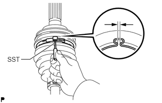
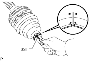
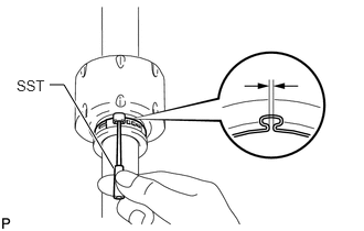
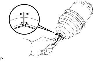
Using SST, adjust the clearance of the clamp.
09240-00020
Standard clearance
0.5 to 1.5 mm (0.0197 to 0.0591 in.)
Note:If the measured value exceeds the specified value, retighten the clamp.
INSTALL FRONT AXLE OUTBOARD JOINT BOOT CLAMP LH
Secure the outboard joint boot clamp to the boot.
-
Place SST onto the outboard joint boot clamp.
09521-24010
Table 3. Text in Illustration *a
Turn
*b
Hold
Tighten SST so that the outboard joint boot clamp is pinched.
Note:Do not overtighten SST.
-
Using SST, adjust the clearance of the clamp.
09240-00020
Standard clearance
0.5 to 1.5 mm (0.0197 to 0.0591 in.)
Note:If the measured value exceeds the specified value, retighten the clamp.
INSTALL FRONT DRIVE SHAFT DAMPER RH
Install the drive shaft damper to the drive shaft.
-
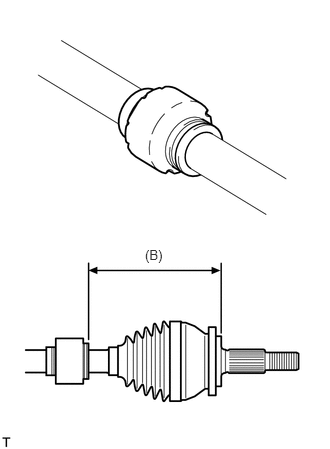
Adjust the position of the damper so that the dimension is as described below.
Standard Distance (B)
Engine Type
Transaxle Type
Specified Condition
1ZR-FAE
Manual transaxle
434 to 438 mm (1.424 to 1.430 ft.)
2ZR-FAE
Continuously variable transaxle
Manual transaxle
433 to 439 mm (1.421 to 1.439 ft.)
INSTALL DRIVE SHAFT DAMPER SETTING CLAMP RH
Install a new drive shaft damper clamp to the damper.
Note:Be sure to install the clamp on the inboard joint side in the correct position.
-
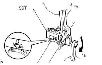
Place SST onto the damper clamp.
09521-24010
Table 4. Text in Illustration *a
Turn
*b
Hold
Tighten SST so that the damper clamp is pinched.
Note:Do not overtighten SST.
-
Using SST, adjust the clearance of the damper clamp.
09240-00020
Standard clearance
0.5 to 1.5 mm (0.0197 to 0.0591 in.)
Note:If the clearance is more than the standard, retighten the clamp.
INSTALL FRONT DRIVE INBOARD JOINT LH
Wrap the spline of the outboard joint shaft with protective tape to prevent the boot from being damaged.
Install new parts to the outboard joint shaft in the following order.
Inboard joint boot clamp
Inboard joint boot
No. 2 inboard joint boot clamp
-
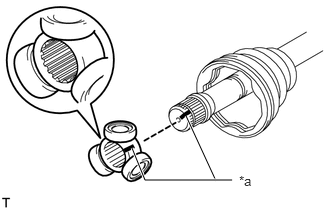
Place the beveled side of the tripod axial spline toward the outboard joint.
Align the matchmarks placed before removal.
Table 5. Text in Illustration *a
Matchmark
Using a brass bar and hammer, tap the tripod onto the drive shaft.
Note:Do not tap the rollers.
Be sure to install the tripod in the correct direction.
Pack the inboard joint shaft and boot with grease from the boot kit.
Standard Grease Capacity
Engine Type
Transaxle Type
Grease Capacity
1ZR-FAE
Manual transaxle
155 to 171 g (5.47 to 6.03 oz.)
2ZR-FAE
Continuously variable transaxle
Manual transaxle
for LH Side:
172 to 188 g (6.07 to 6.63 oz.)
for RH Side:
170 to 186 g (6.00 to 6.56 oz.)
-
Using a snap ring expander, install a new shaft snap ring.
-
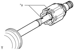
Align the matchmarks and install the inboard joint to the outboard joint shaft.
Table 6. Text in Illustration *a
Matchmark
INSTALL FRONT DRIVE INBOARD JOINT RH
Tip:Use the same procedures described for the LH side.
INSTALL INBOARD JOINT BOOT
Install the inboard joint boot to the inboard joint.
-
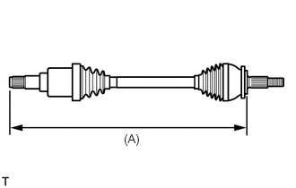
Check that the 2 boots are not stretched or contracted when the drive shaft is at the standard length.
Length (A) (for LH Side)
Engine Type
Transaxle Type
Specified Condition
1ZR-FAE
Manual transaxle
589.25 mm (1.93 ft.)
2ZR-FAE
Continuously variable transaxle
Manual transaxle
590.4 mm (1.94 ft.)
Length (A) (for RH Side)
Engine Type
Transaxle Type
Specified Condition
1ZR-FAE
Manual transaxle
875.25 mm (2.87 ft.)
2ZR-FAE
Continuously variable transaxle
Manual transaxle
869.3 mm (2.85 ft.)
INSTALL FRONT AXLE INBOARD JOINT BOOT CLAMP LH
Secure the inboard joint boot clamp to the boot.
-
Place SST onto the inboard joint boot clamp.
09521-24010
Table 7. Text in Illustration *a
Turn
*b
Hold
Tighten SST so that the clamp is pinched.
Note:Do not overtighten SST.
-
Using SST, adjust the clearance of the clamp.
09240-00020
Standard clearance
0.5 to 1.5 mm (0.0197 to 0.0591 in.)
Note:If the clearance is more than the standard, retighten the clamp.
INSTALL FRONT AXLE INBOARD JOINT BOOT CLAMP RH
Tip:Use the same procedures described for the LH side.
INSTALL FRONT NO. 2 AXLE INBOARD JOINT BOOT CLAMP LH
Secure the inboard joint boot clamp to the boot.
-
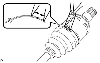
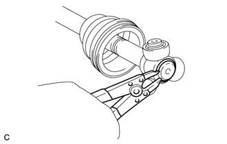
Using needle-nose pliers, install the axle inboard joint boot clamp as shown in the illustration.
Note:Be careful not to damage the boot.
INSTALL FRONT NO. 2 AXLE INBOARD JOINT BOOT CLAMP RH
Tip:Use the same procedures described for the LH side.
INSTALL FRONT DRIVE SHAFT HOLE SNAP RING LH
Install a new hole snap ring.
INSTALL FRONT DRIVE SHAFT HOLE SNAP RING RH
Tip:Use the same procedures described for the LH side.
INSPECT DRIVE SHAFT