REAR AXLE BEAM INSTALLATION
PROCEDURE
INSTALL REAR AXLE CARRIER BUSHING LH
When reusing the rear axle beam assembly:
-
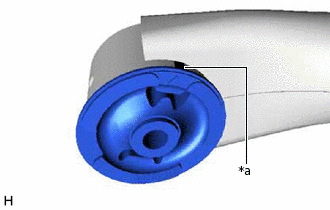
*a
Matchmark
Align the arrow mark on a new rear axle carrier bushing LH with the matchmark on the rear axle beam assembly and temporarily install the rear axle carrier bushing LH to the rear axle beam assembly.
Note:Be sure to install the rear axle carrier bushing LH in the same direction as it was before removal. The rear axle carrier bushing LH has to be installed in a specific direction.
-
When using a new rear axle beam assembly:
-
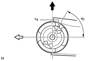
*a
Arrow mark
*b
60°

Upper Side of the Vehicle

Front of the Vehicle
Temporarily install a new rear axle carrier bushing LH as shown in the illustration.
-
-
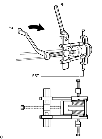
*a
Turn
*b
Hold
Using SST, install the rear axle carrier bushing LH to the rear axle beam assembly.
09631-32020
09710-28031
09711-02020
09950-40011
09951-04020
09952-04010
09953-04030
09954-04020
09955-04051
09957-04010
09958-04011
09950-60010
09951-00650
09950-60020
Note:Do not damage the rubber portion when installing the rear axle carrier bushing LH.
Apply grease to the threads and tip of the SST center bolt before use.
INSTALL REAR AXLE CARRIER BUSHING RH
Tip:Perform the same procedure as for the LH side.
TEMPORARILY INSTALL REAR AXLE BEAM ASSEMBLY
Slowly jack up the rear axle beam assembly with an engine lifter using 2 wooden blocks and 2 attachments or equivalent tools, and temporarily install the rear axle beam assembly to the body with the 2 bolts (B).
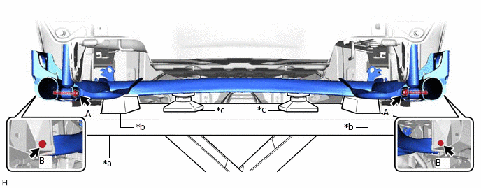
*a
Engine Lifter
*b
Wooden Block
*c
Attachment
-
-
CAUTION:Make sure to secure the rear axle beam assembly to prevent it from dropping.
Temporarily install the rear axle beam assembly to the rear shock absorber assemblies LH and RH with the 2 bolts (A).
INSTALL REAR UPPER COIL SPRING INSULATOR LH
INSTALL REAR UPPER COIL SPRING INSULATOR RH
Tip:Perform the same procedure as for the LH side.
INSTALL REAR LOWER COIL SPRING INSULATOR LH
INSTALL REAR LOWER COIL SPRING INSULATOR RH
Tip:Perform the same procedure as for the LH side.
INSTALL REAR COIL SPRING LH
INSTALL REAR COIL SPRING RH
Tip:Perform the same procedure as for the LH side.
INSTALL REAR AXLE HUB AND BEARING ASSEMBLY LH
INSTALL REAR AXLE HUB AND BEARING ASSEMBLY RH
Tip:Perform the same procedure as for the LH side.
INSTALL REAR BRAKE DRUM SUB-ASSEMBLY
Install the 2 rear brake drum sub-assemblies.
INSTALL REAR NO. 4 BRAKE TUBE
Install the rear No. 4 brake tube to the rear axle beam assembly with the clamp.
Using a union nut wrench, install the rear No. 4 brake tube to the rear brake wheel cylinder assembly LH.
15.2 N*m
155 kgf*cm
11 ft.*lbf
Note:Do not kink or damage the brake line.
Do not allow any foreign matter such as dirt or dust to enter the brake line from the connecting parts.
Use the formula to calculate special torque values for situations where the union nut wrench is combined with a torque wrench.
Install the rear brake tube flexible hose to the rear axle beam assembly with a new clip.
Note:Install the clip as far as it will go.
Using a union nut wrench, connect the rear brake tube flexible hose to the rear No. 4 brake tube while holding the rear brake tube flexible hose with a wrench.
15.2 N*m
155 kgf*cm
11 ft.*lbf
Note:Do not kink or damage the brake line.
Do not allow any foreign matter such as dirt or dust to enter the brake line from the connecting parts.
Use the formula to calculate special torque values for situations where the union nut wrench is combined with a torque wrench.
INSTALL REAR NO. 3 BRAKE TUBE
Tip:Perform the same procedure as for the rear No. 4 brake tube.
INSTALL NO. 3 PARKING BRAKE CABLE ASSEMBLY
Install the No. 3 parking brake cable assembly to the rear axle beam assembly with the bolt and nut.
6.0 N*m
61 kgf*cm
53 in.*lbf
INSTALL NO. 2 PARKING BRAKE CABLE ASSEMBLY
Tip:Perform the same procedure as for the No. 3 parking brake cable assembly.
INSTALL REAR SPEED SENSOR LH
INSTALL REAR SPEED SENSOR RH
Tip:Perform the same procedure as for the LH side.
BLEED BRAKE LINE
ADJUST REAR DRUM BRAKE SHOE CLEARANCE
FULLY TIGHTEN HEXALOBULAR SCREW
INSTALL REAR WHEELS
STABILIZE SUSPENSION
INSTALL REAR AXLE BEAM ASSEMBLY
INSPECT REAR WHEEL ALIGNMENT
ALIGN FRONT WHEELS FACING STRAIGHT AHEAD (w/ VSC)
PERFORM ACCELERATION SENSOR CALIBRATION (w/ VSC)
CHECK FOR SPEED SENSOR SIGNAL
w/o VSC:Click here
w/ VSC:Click here