SFI SYSTEM, Diagnostic DTC:U0101
| DTC Code | DTC Name |
|---|---|
| U0101 | Lost Communication With TCM |
DESCRIPTION
The Engine Control Module (ECM) communicates with the Transmission Control Module (TCM) through the Controller Area Network (CAN).
If there is a problem in this communication, the ECM stores a DTC.
DTC No. |
Detection Item |
DTC Detection Condition |
Trouble Area |
MIL |
Memory |
|---|---|---|---|---|---|
U0101 |
Lost Communication With TCM |
All of the following conditions are met for 0.49 seconds (1 trip detection logic):
|
|
Comes on |
DTC stored (for MMT models) - (for M/T models) |
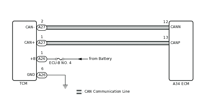
WIRING DIAGRAM
CONFIRMATION DRIVING PATTERN
DTC U0101 is detected when the ignition switch is ON and wait for 2 seconds.
CAUTION / NOTICE / HINT
After replacing the ECM, perform idle learning.
Inspect the fuses for circuits related to this system before performing the following procedure.
If the CAN communication malfunctions, there is no data output from the ECM. In this case, some of the freeze frame data are not correct and not identical with the ECM data, however the ECM data are correct.
Read freeze frame data using the GTS. Freeze frame data records the engine condition when malfunctions are detected. When troubleshooting, freeze frame data can help determine if the vehicle was moving or stationary, if the engine was warmed up or not, if the air fuel ratio was lean or rich, and other data from the time the malfunction occurred.
PROCEDURE
CHECK ANY OTHER DTCS OUTPUT (IN ADDITION TO DTC U0101)
Connect the GTS to the DLC3.
Turn the ignition switch to ON.
Turn the GTS on.
Enter the following menus: System Select / Health Check.
Read the DTCs.
Result
Result
Proceed to
DTC U0101 is output
A
DTC U0101 and other DTCs are output
B
Tip:If any DTCs other than DTC U0101 are output, troubleshoot those DTCs first.
B GO TO DTC CHART
CHECK TERMINAL VOLTAGE (POWER SOURCE OF TCM)
Disconnect the TCM connector.
Measure the voltage according to the value(s) in the table below.
Standard Voltage
Tester Connection
Condition
Specified Condition
A26-1 (+B) - A26-6 (GND)
Always
11 to 14 V
Result
Proceed to
OK
NG
CHECK HARNESS AND CONNECTOR (TCM - ECM)
Disconnect the TCM connector.
Disconnect the ECM connector.
Measure the resistance according to the value(s) in the table below.
Standard Resistance
Tester Connection
Condition
Specified Condition
A27-1 (CAN+) - A34-13 (CANP)
Always
Below 1 Ω
A27-2 (CAN-) - A34-12 (CANN)
Always
Below 1 Ω
A27-1 (CAN+) or A34-13 (CANP) - Body ground
Always
10 kΩ or higher
A27-2 (CAN-) or A34-12 (CANN) - Body ground
Always
10 kΩ or higher
Result
Proceed to
OK
NG
NG REPAIR OR REPLACE HARNESS OR CONNECTOR
REPLACE TCM
Replace the TCM.
Result
Proceed to
NEXT
CHECK WHETHER DTC OUTPUT RECURS (DTC U0101)
Connect the GTS to the DLC3.
Turn the ignition switch to ON.
Turn the GTS on.
Clear the DTCs.
Powertrain > Engine and ECT > Clear DTCs
Turn the ignition switch off and wait for at least 30 seconds.
Turn the ignition switch to ON and turn the GTS on.
Enter the following menus: Powertrain / Engine and ECT / Trouble Codes.
Read the DTCs.
Powertrain > Engine and ECT > Trouble Codes
Result
Result
Proceed to
DTCs are not output
A
DTC U0101 is output
B
A END