POWER WINDOW MASTER SWITCH INSPECTION
PROCEDURE
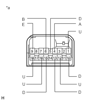
INSPECT POWER WINDOW REGULATOR MASTER SWITCH ASSEMBLY (for Models with Jam Protection Function on 4 Windows)
-
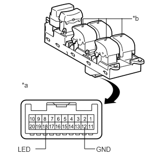
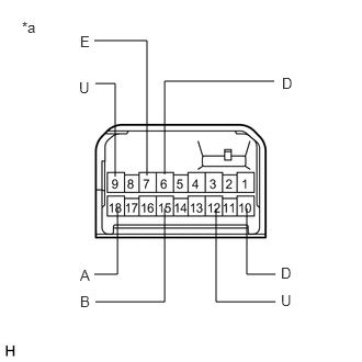
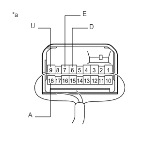
*a
Component without harness connected
(Power Window Regulator Master Switch Assembly)
*b
LED
Check that the LEDs illuminate.
Apply battery voltage to the power window regulator master switch assembly and check that the LEDs illuminate.
OK
Measurement Condition
Specified Condition
Battery positive (+) → 18 (LED)
Battery negative (-) → 12 (GND)
LEDs illuminate
If the result is not as specified, replace the power window regulator master switch assembly.
-
INSPECT POWER WINDOW REGULATOR MASTER SWITCH ASSEMBLY (for LHD) (for Models with Jam Protection Function on Driver Door Window Only)
-
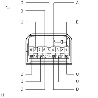
*a
Component without harness connected
(Power Window Regulator Master Switch Assembly (w/ Rear Power Window))
Check the switch function. (w/ Rear Power Window)
Turn the window lock switch off and operate the switches on the power window regulator master switch assembly.
Measure the resistance according to the value(s) in the table below.
Standard Resistance
Table 1. Driver Side Switch Tester Connection
Condition
Specified Condition
4 (A) - 1 (E)
AUTO UP
Below 1 Ω
8 (U) - 1 (E)
AUTO UP
Below 1 Ω
8 (U) - 1 (E)
MANUAL UP
Below 1 Ω
5 (D) - 1 (E)
MANUAL DOWN
Below 1 Ω
4 (A) - 1 (E)
AUTO DOWN
Below 1 Ω
5 (D) - 1 (E)
AUTO DOWN
Below 1 Ω
Standard Resistance
Table 2. Front Passenger Side Switch Tester Connection
Condition
Specified Condition
6 (B) - 16 (U)
UP
Below 1 Ω
1 (E) - 15 (D)
UP
Below 1 Ω
1 (E) - 16 (U)
Off
Below 1 Ω
1 (E) - 15 (D)
Off
Below 1 Ω
1 (E) - 16 (U)
DOWN
Below 1 Ω
6 (B) - 15 (D)
DOWN
Below 1 Ω
Standard Resistance
Table 3. Rear RH Side Switch Tester Connection
Condition
Specified Condition
6 (B) - 10 (U)
UP
Below 1 Ω
1 (E) - 18 (D)
UP
Below 1 Ω
1 (E) - 18 (D)
Off
Below 1 Ω
1 (E) - 10 (U)
Off
Below 1 Ω
6 (B) - 18 (D)
DOWN
Below 1 Ω
1 (E) - 10 (U)
DOWN
Below 1 Ω
Standard Resistance
Table 4. Rear LH Side Switch Tester Connection
Condition
Specified Condition
6 (B) - 12 (U)
UP
Below 1 Ω
1 (E) - 13 (D)
UP
Below 1 Ω
1 (E) - 13 (D)
Off
Below 1 Ω
1 (E) - 12 (U)
Off
Below 1 Ω
6 (B) - 13 (D)
DOWN
Below 1 Ω
1 (E) - 12 (U)
DOWN
Below 1 Ω
If the result is not as specified, replace the power window regulator master switch assembly.
-
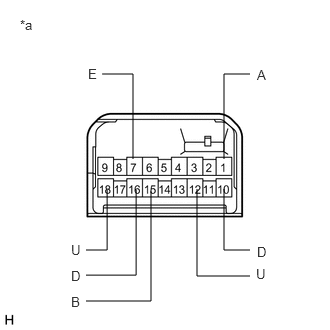
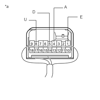
*a
Component without harness connected
(Power Window Regulator Master Switch Assembly (w/o Rear Power Window))
Check the switch function. (w/o Rear Power Window)
Turn the window lock switch off and operate the switches on the power window regulator master switch assembly.
Measure the resistance according to the value(s) in the table below.
Standard Resistance
Table 5. Driver Side Switch Tester Connection
Condition
Specified Condition
1 (A) - 7 (E)
AUTO UP
Below 1 Ω
18 (U) - 7 (E)
AUTO UP
Below 1 Ω
18 (U) - 7 (E)
MANUAL UP
Below 1 Ω
10 (D) - 7 (E)
MANUAL DOWN
Below 1 Ω
1 (A) - 7 (E)
AUTO DOWN
Below 1 Ω
10 (D) - 7 (E)
AUTO DOWN
Below 1 Ω
Standard Resistance
Table 6. Front Passenger Side Switch Tester Connection
Condition
Specified Condition
15 (B) - 12 (U)
UP
Below 1 Ω
7 (E) - 16 (D)
UP
Below 1 Ω
7 (E) - 12 (U)
Off
Below 1 Ω
7 (E) - 16 (D)
Off
Below 1 Ω
7 (E) - 12 (U)
DOWN
Below 1 Ω
15 (B) - 16 (D)
DOWN
Below 1 Ω
If the result is not as specified, replace the power window regulator master switch assembly.
-
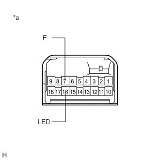
*a
Component without harness connected
(Power Window Regulator Master Switch Assembly (w/ Rear Power Window))
Check that the LEDs illuminate. (w/ Rear Power Window)
Apply battery voltage to the power window regulator master switch assembly and check that the LEDs illuminate.
OK
Measurement Condition
Specified Condition
Battery positive (+) → Terminal 3 (LED)
Battery negative (-) → Terminal 1 (E)
LEDs illuminate
If the result is not as specified, replace the power window regulator master switch assembly.
-
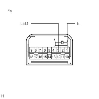
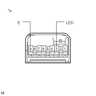
*a
Component without harness connected
(Power Window Regulator Master Switch Assembly (w/o Rear Power Window))
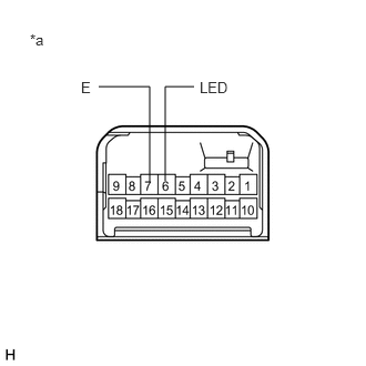
Check that the LEDs illuminate. (w/o Rear Power Window)
Apply battery voltage to the power window regulator master switch assembly and check that the LEDs illuminate.
OK
Measurement Condition
Specified Condition
Battery positive (+) → Terminal 6 (LED)
Battery negative (-) → Terminal 7 (E)
LEDs illuminate
If the result is not as specified, replace the power window regulator master switch assembly.
-
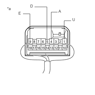
*a
Component with harness connected
(Power Window Regulator Master Switch Assembly)
Check the switch function. (w/ Rear Power Window)
Reconnect the power window regulator master switch assembly.
Measure the voltage according to the value(s) in the table below.
Standard Voltage
Tester Connection
Condition
Specified Condition
8 (U) - 1 (E)
Ignition switch ON, driver door power window regulator switch off
11 to 14 V
8 (U) - 1 (E)
Ignition switch ON, driver door power window regulator switch up (Auto up position)
Below 1 V
8 (U) - 1 (E)
Ignition switch ON, driver door power window regulator switch up (Manual operation)
Below 1 V
4 (A) - 1 (E)
Ignition switch ON, driver door power window regulator switch off
11 to 14 V
4 (A) - 1 (E)
Ignition switch ON, driver door power window regulator switch up (Auto up position)
Below 1 V
4 (A) - 1 (E)
Ignition switch ON, driver door power window regulator switch down (Auto down position)
Below 1 V
5 (D) - 1 (E)
Ignition switch ON, driver door power window regulator switch off
11 to 14 V
5 (D) - 1 (E)
Ignition switch ON, driver door power window regulator switch down (Auto down position)
Below 1 V
5 (D) - 1 (E)
Ignition switch ON, driver door power window regulator switch down (Manual operation)
Below 1 V
If the result is not as specified, replace the power window regulator master switch assembly.
-
*a
Component with harness connected
(Power Window Regulator Master Switch Assembly)
Check the switch function. (w/o Rear Power Window)
Reconnect the power window regulator master switch assembly.
Measure the voltage according to the value(s) in the table below.
Standard Voltage
Tester Connection
Condition
Specified Condition
18 (U) - 7 (E)
Ignition switch ON, driver door power window regulator switch off
11 to 14 V
18 (U) - 7 (E)
Ignition switch ON, driver door power window regulator switch up (Auto up position)
Below 1 V
18 (U) - 7 (E)
Ignition switch ON, driver door power window regulator switch up (Manual operation)
Below 1 V
1 (A) - 7 (E)
Ignition switch ON, driver door power window regulator switch off
11 to 14 V
1 (A) - 7 (E)
Ignition switch ON, driver door power window regulator switch up (Auto up position)
Below 1 V
1 (A) - 7 (E)
Ignition switch ON, driver door power window regulator switch down (Auto down position)
Below 1 V
10 (D) - 7 (E)
Ignition switch ON, driver door power window regulator switch off
11 to 14 V
10 (D) - 7 (E)
Ignition switch ON, driver door power window regulator switch down (Auto down position)
Below 1 V
10 (D) - 7 (E)
Ignition switch ON, driver door power window regulator switch down (Manual operation)
Below 1 V
If the result is not as specified, replace the power window regulator master switch assembly.
-
INSPECT POWER WINDOW REGULATOR MASTER SWITCH ASSEMBLY (for RHD) (for Models with Jam Protection Function on Driver Door Window Only)
-
*a
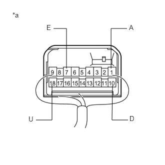
Component without harness connected
(Power Window Regulator Master Switch Assembly (w/ Rear Power Window))
Check the switch function. (w/ Rear Power Window)
Turn the window lock switch off and operate the switches on the power window regulator master switch assembly.
Measure the resistance according to the value(s) in the table below.
Standard Resistance
Table 7. Driver Side Switch Tester Connection
Condition
Specified Condition
4 (A) - 9 (E)
AUTO UP
Below 1 Ω
1 (U) - 9 (E)
AUTO UP
Below 1 Ω
1 (U) - 9 (E)
MANUAL UP
Below 1 Ω
5 (D) - 9 (E)
MANUAL DOWN
Below 1 Ω
4 (A) - 9 (E)
AUTO DOWN
Below 1 Ω
5 (D) - 9 (E)
AUTO DOWN
Below 1 Ω
Standard Resistance
Table 8. Front Passenger Side Switch Tester Connection
Condition
Specified Condition
6 (B) - 12 (U)
UP
Below 1 Ω
9 (E) - 13 (D)
UP
Below 1 Ω
9 (E) - 12 (U)
Off
Below 1 Ω
9 (E) - 13 (D)
Off
Below 1 Ω
9 (E) - 12 (U)
DOWN
Below 1 Ω
6 (B) - 13 (D)
DOWN
Below 1 Ω
Standard Resistance
Table 9. Rear RH Side Switch Tester Connection
Condition
Specified Condition
6 (B) - 16 (U)
UP
Below 1 Ω
9 (E) - 15 (D)
UP
Below 1 Ω
9 (E) - 15 (D)
Off
Below 1 Ω
9 (E) - 16 (U)
Off
Below 1 Ω
6 (B) - 15 (D)
DOWN
Below 1 Ω
9 (E) - 16 (U)
DOWN
Below 1 Ω
Standard Resistance
Table 10. Rear LH Side Switch Tester Connection
Condition
Specified Condition
6 (B) - 18 (U)
UP
Below 1 Ω
9 (E) - 10 (D)
UP
Below 1 Ω
9 (E) - 10 (D)
Off
Below 1 Ω
9 (E) - 18 (U)
Off
Below 1 Ω
6 (B) - 10 (D)
DOWN
Below 1 Ω
9 (E) - 18 (U)
DOWN
Below 1 Ω
If the result is not as specified, replace the power window regulator master switch assembly.
-
*a
Component without harness connected
(Power Window Regulator Master Switch Assembly (w/o Rear Power Window))
Check the switch function. (w/o Rear Power Window)
Turn the window lock switch off and operate the switches on the power window regulator master switch assembly.
Measure the resistance according to the value(s) in the table below.
Standard Resistance
Table 11. Driver Side Switch Tester Connection
Condition
Specified Condition
18 (A) - 7 (E)
AUTO UP
Below 1 Ω
9 (U) - 7 (E)
AUTO UP
Below 1 Ω
9 (U) - 7 (E)
MANUAL UP
Below 1 Ω
6 (D) - 7 (E)
MANUAL DOWN
Below 1 Ω
18 (A) - 7 (E)
AUTO DOWN
Below 1 Ω
6 (D) - 7 (E)
AUTO DOWN
Below 1 Ω
Standard Resistance
Table 12. Front Passenger Side Switch Tester Connection
Condition
Specified Condition
15 (B) - 12 (U)
UP
Below 1 Ω
7 (E) - 10 (D)
UP
Below 1 Ω
7 (E) - 12 (U)
Off
Below 1 Ω
7 (E) - 10 (D)
Off
Below 1 Ω
7 (E) - 12 (U)
DOWN
Below 1 Ω
15 (B) - 10 (D)
DOWN
Below 1 Ω
If the result is not as specified, replace the power window regulator master switch assembly.
-
*a
Component without harness connected
(Power Window Regulator Master Switch Assembly (w/ Rear Power Window))
Check that the LEDs illuminate. (w/ Rear Power Window)
Apply battery voltage to the power window regulator master switch assembly and check that the LEDs illuminate.
OK
Measurement Condition
Specified Condition
Battery positive (+) → Terminal 3 (LED)
Battery negative (-) → Terminal 9 (E)
LEDs illuminate
If the result is not as specified, replace the power window regulator master switch assembly.
-
*a
Component without harness connected
(Power Window Regulator Master Switch Assembly (w/o Rear Power Window))
Check that the LEDs illuminate. (w/o Rear Power Window)
Apply battery voltage to the power window regulator master switch assembly and check that the LEDs illuminate.
OK
Measurement Condition
Specified Condition
Battery positive (+) → Terminal 16 (LED)
Battery negative (-) → Terminal 7 (E)
LEDs illuminate
If the result is not as specified, replace the power window regulator master switch assembly.
-
*a
Component with harness connected
(Power Window Regulator Master Switch Assembly)
Check the switch function. (w/ Rear Power Window)
Reconnect the power window regulator master switch assembly.
Measure the voltage according to the value(s) in the table below.
Standard Voltage
Tester Connection
Condition
Specified Condition
1 (U) - 9 (E)
Ignition switch ON, driver door power window regulator switch off
11 to 14 V
1 (U) - 9 (E)
Ignition switch ON, driver door power window regulator switch up (Auto up position)
Below 1 V
1 (U) - 9 (E)
Ignition switch ON, driver door power window regulator switch up (Manual operation)
Below 1 V
4 (A) - 9 (E)
Ignition switch ON, driver door power window regulator switch off
11 to 14 V
4 (A) - 9 (E)
Ignition switch ON, driver door power window regulator switch up (Auto up position)
Below 1 V
4 (A) - 9 (E)
Ignition switch ON, driver door power window regulator switch down (Auto down position)
Below 1 V
5 (D) - 9 (E)
Ignition switch ON, driver door power window regulator switch off
11 to 14 V
5 (D) - 9 (E)
Ignition switch ON, driver door power window regulator switch down (Auto down position)
Below 1 V
5 (D) - 9 (E)
Ignition switch ON, driver door power window regulator switch down (Manual operation)
Below 1 V
If the result is not as specified, replace the power window regulator master switch assembly.
-
*a
Component with harness connected
(Power Window Regulator Master Switch Assembly)
Check the switch function. (w/o Rear Power Window)
Reconnect the power window regulator master switch assembly.
Measure the voltage according to the value(s) in the table below.
Standard Voltage
Tester Connection
Condition
Specified Condition
9 (U) - 7 (E)
Ignition switch ON, driver door power window regulator switch off
11 to 14 V
9 (U) - 7 (E)
Ignition switch ON, driver door power window regulator switch up (Auto up position)
Below 1 V
9 (U) - 7 (E)
Ignition switch ON, driver door power window regulator switch up (Manual operation)
Below 1 V
18 (A) - 7 (E)
Ignition switch ON, driver door power window regulator switch off
11 to 14 V
18 (A) - 7 (E)
Ignition switch ON, driver door power window regulator switch up (Auto up position)
Below 1 V
18 (A) - 7 (E)
Ignition switch ON, driver door power window regulator switch down (Auto down position)
Below 1 V
6 (D) - 7 (E)
Ignition switch ON, driver door power window regulator switch off
11 to 14 V
6 (D) - 7 (E)
Ignition switch ON, driver door power window regulator switch down (Auto down position)
Below 1 V
6 (D) - 7 (E)
Ignition switch ON, driver door power window regulator switch down (Manual operation)
Below 1 V
If the result is not as specified, replace the power window regulator master switch assembly.
-