TURBOCHARGER (w/o EGR Cooler) INSPECTION
-
VISUALLY CHECK TURBOCHARGER SUB-ASSEMBLY
-
Check for deformation and cracks in the turbine wheel on the exhaust side.
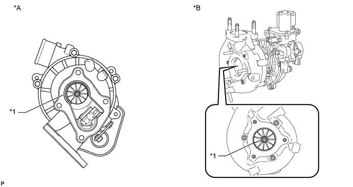
Text in Illustration *A w/o Intercooler *B w/ Intercooler *1 Turbine Wheel - - If the turbine wheel is cracked or deformed, replace the turbocharger sub-assembly.
-
-
INSPECT AXIAL PLAY OF TURBINE SHAFT
-
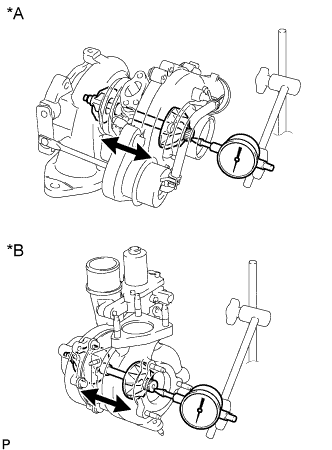
Text in Illustration *A w/o Intercooler *B w/ Intercooler Using a dial indicator, insert the needle of the dial indicator into the exhaust side of the turbine shaft.
Note
Turbocharger sub-assembly and dial indicators are surely fixed when performing measurement.
-
Move the turbine shaft in an axial direction and measure the axial play of the turbine shaft.
Maximum Axial Play Item Specified Condition w/o Intercooler 0.08 mm (0.0031 in.) w/ Intercooler 0.11 mm (0.00433 in.) If the axial play is more than the maximum, replace the turbocharger sub-assembly.
-
-
INSPECT RADIAL PLAY OF TURBINE SHAFT (w/o Intercooler)
-
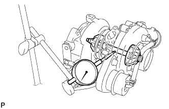
Using a dial indicator, insert the needle of the dial indicator into the oil outlet hole, and set it in the center of the turbine shaft.
-
Move the turbine shaft in a radial direction and measure the radial play of the turbine shaft.
Maximum Radial Play 0.110 mm (0.0043 in.) If the radial play is more than the maximum, replace the turbocharger sub-assembly.
-
-
CHECK TURBINE SHAFT ROTATION
-
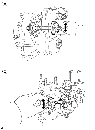
Text in Illustration *A w/o Intercooler *B w/ Intercooler Rotate the turbine wheel on the exhaust side with your finger and check that it rotates smoothly.
Tech Tips
Even if it takes a little effort to rotate the turbine wheel, this is not a problem.
If the turbine wheel does not rotate smoothly, replace the turbocharger sub-assembly.
-
-
INSPECT ACTUATOR AND WASTE GATE VALVE OPERATION (w/o Intercooler)
-
Disconnect the actuator hose from the compressor housing.
-
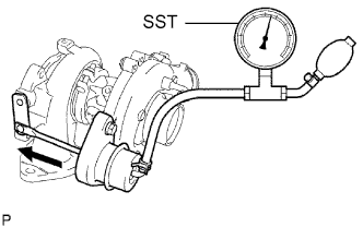
Using SST, apply pressure to the actuator.
- SST
- 09992-00242
Valve opening pressure Specified pressure* (See attached table below) Note
Never apply more than predetermined maximum pressure*to the actuator.
Tech Tips
*: For the specifications, refer to the table below.
-
Check that the actuator push rod moves and that the waste gate valve opens.
Specifications Valve Opening Pressure
(Gauge Pressure)
Maximum Pressure
(Gauge Pressure)
Rod Stroke
(Reference)
108 kPa (1.10 kgf/cm2, 15 psi)
136 kPa (1.40 kgf/cm2, 20 psi)
2.0 to 4.50 mm (0.0787 to 0.177 in.) If the rod does not move, replace the turbocharger sub-assembly.
-
Reconnect the actuator hose to the compressor housing.
-