CYLINDER HEAD INSTALLATION
Note
-
When replacing the injectors (including shuffling the injectors between the cylinders), common rail or cylinder head, it is necessary to replace the injection pipes with new ones.
-
When replacing the fuel supply pump, common rail, cylinder block, cylinder head, cylinder head gasket or timing gear case, it is necessary to replace the fuel inlet pipe with a new one.
-
After removing the injection pipes, clean them with a brush and compressed air.
-
INSTALL CYLINDER HEAD GASKET
-
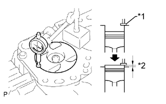
Text in Illustration *1 Measuring Tip *2 Protrusion Find where the piston head protrudes most by slowly turning the crankshaft clockwise and counterclockwise.
-
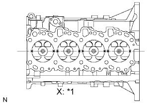
Text in Illustration *1 Measuring Point Measure the piston protrusion of each cylinder at 2 points as shown in the illustration.
-
For the piston protrusion value of each cylinder, use the average of the 2 measurements of each cylinder.
Piston protrusion 0.005 to 0.255 mm (0.0002 to 0.0100 in.) Tech Tips
After installing the piston and connecting rod assembly, if the protrusion is not as specified, remove the piston and connecting rod assembly and reinstall them.
-
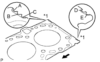
Text in Illustration *1 Cutout Mark 
Front Select a new cylinder head gasket.
Tech Tips
New cylinder head gaskets are available in 5 sizes, and are marked A, B, C, D or E.
New Cylinder Head Gasket Thickness Mark Specified Condition A 0.80 to 0.90 mm (0.0315 to 0.0354 in.) B 0.85 to 0.95 mm (0.0335 to 0.0374 in.) C 0.90 to 1.00 mm (0.0354 to 0.0394 in.) D 0.95 to 1.05 mm (0.0374 to 0.0413 in.) E 1.00 to 1.10 mm (0.0394 to 0.0433 in.)
-
Select the largest piston protrusion value from the measurements made. Then select a new gasket according to the table below.
Gasket Size Item Specified Condition Piston protrusion 0.005 to 0.054 mm (0.0002 to 0.0021 in.) 0.055 to 0.104 mm (0.0022 to 0.0041 in.) 0.105 to 0.154 mm (0.0041 to 0.0061 in.) 0.155 to 0.204 mm (0.0061 to 0.0080 in.) 0.205 to 0.255 mm (0.0081 to 0.0100 in.) Gasket to be used A B C D E
-
-
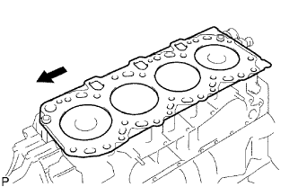
Place the cylinder head gasket on the cylinder block.
Text in Illustration Front Note
Make sure the gasket is installed facing the proper direction.
-
-
INSTALL CYLINDER HEAD SUB-ASSEMBLY
Tech Tips
-
The cylinder head bolts are tightened in 3 progressive steps.
-
If any bolt is broken or deformed, replace it Click here.
-
Place the cylinder head on the cylinder head gasket.
-
Apply a light coat of engine oil to the threads and under the heads of the cylinder head bolts.
-
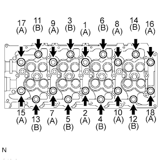
Install the 18 washers with the 18 cylinder head bolts, and uniformly tighten the bolts in several passes in the sequence shown in the illustration.
- Torque:
- 85 N*m { 867 kgf*cm, 63 ft.*lbf }
Standard Bolt Length Item Specified Condition A 110 mm (4.33 in.) B 167 mm (6.57 in.) If any one the cylinder head bolts does not meet the torque specification, replace it.
-
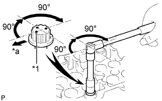
*1 Painted Mark *a Front Mark the front of each cylinder head bolt with paint.
-
Further tighten the cylinder head bolts by 90° in the sequence shown in the illustration.
-
Tighten the cylinder head bolts by an additional 90°.
-
Check that the painted marks are now facing rearward.
-
-
INSTALL VALVE LIFTER
-
Install the valve lifters.
-
Check that each valve lifter rotates smoothly by hand.
-
-
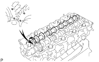
INSTALL CAMSHAFT
-
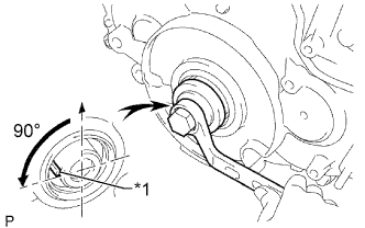
Text in Illustration *1 Key Using the crankshaft pulley bolt, set the No. 1 cylinder to 90° BTDC/compression.
Tech Tips
Set the No. 1 cylinder to 90° BTDC/compression to prevent the top of the piston from hitting against the valve head.
-
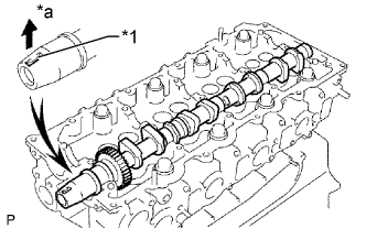
Install the camshaft.
-
Apply engine oil to the thrust portion of the camshaft.
-
Place the camshaft on the cylinder head with the key groove facing upward.
Text in Illustration *1 Key Groove *a Upward -
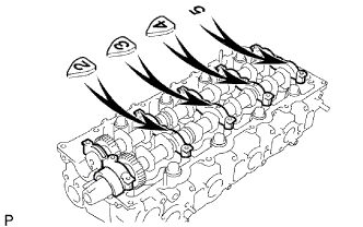
Align the timing marks (1-dot marks) of the camshaft drive and driven main gears and set the No. 2 camshaft in place.
-
-
Remove any old seal packing (FIPG material) from the camshaft bearing cap.
-
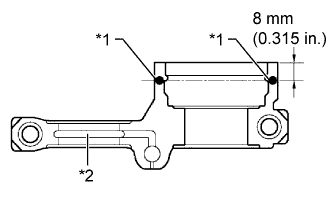
Text in Illustration *1 Seal Packing *2 Oil Passage Apply seal packing to the specified areas shown in the illustration.
Seal packing Toyota Genuine Seal Packing Black, Three Bond 1207B or equivalent Standard seal diameter 4 mm (0.16 in.) Note
-
Do not allow seal packing to contact the oil passage of the bearing cap.
-
After applying seal packing, install the camshaft bearing caps within 3 minutes and tighten the bolts within 15 minutes.
-
Do not start the engine for at least 2 hours after installation.
-
-
Install the 5 bearing caps to their proper locations.
-
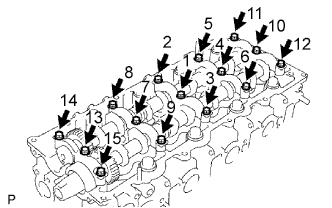
Apply a light coat of engine oil to the threads and under the heads of the bearing cap bolts.
-
Install and uniformly tighten the 15 bearing cap bolts in several passes in the sequence shown in the illustration.
- Torque:
- 19 N*m { 194 kgf*cm, 14 ft.*lbf }
-
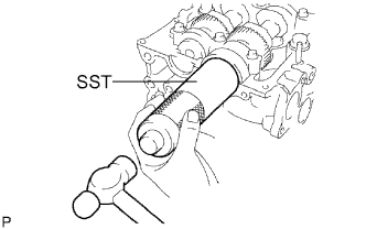
Install a new camshaft oil seal.
-
Apply MP grease to the lip of a new oil seal.
-
Using SST and a hammer, tap in the oil seal until its surface is flush with the surfaces of the camshaft bearing cap and cylinder head.
- SST
- 09608-06041
-
-
-
INSTALL CYLINDER BLOCK INSULATOR
-
Install the cylinder block insulator to the cylinder head.
-
-
INSTALL NO. 2 TIMING BELT COVER
-
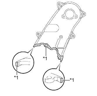
Text in Illustration *1 Seal Packing Apply seal packing (FIPG) to the specified areas shown in the illustration.
Seal packing Toyota Genuine Seal Packing Black, Three Bond 1207B or equivalent Note
After applying seal packing, install the No. 2 timing belt cover within 3 minutes and tighten the bolts and nut within 15 minutes.
-
Clean the bolts and their holes.
-
Apply adhesive to 2 or 3 threads at the end of each of the 4 bolts.
Adhesive Toyota Genuine Adhesive 1324, Three Bond 1324 or equivalent -
Install the No. 2 timing belt cover with the 4 bolts and nut.
- Torque:
- 10 N*m { 102 kgf*cm, 7 ft.*lbf }
-
-
INSTALL CAMSHAFT TIMING PULLEY
-
Install the camshaft timing pulley.
-
Install the bolt of the camshaft timing pulley while holding the camshaft with a wrench.
- Torque:
- 98 N*m { 1000 kgf*cm, 72 ft.*lbf }
-
-
INSTALL TIMING BELT
-
INSPECT AND ADJUST VALVE CLEARANCE
-
INSTALL EXHAUST MANIFOLD
-
w/ EGR Cooler:
Install a new gasket, exhaust manifold, 8 new collars and 8 spacers to the cylinder head with 8 new nuts.
- Torque:
- 40 N*m { 408 kgf*cm, 30 ft.*lbf }
Note
Make sure that the side of the collar with the smaller diameter faces the exhaust manifold.
-
w/o EGR Cooler:
Install a new gasket, exhaust manifold and 8 spacers to the cylinder head with 8 new nuts.
- Torque:
- 40 N*m { 408 kgf*cm, 30 ft.*lbf }
-
-
INSTALL NO. 1 COMPRESSOR MOUNTING BRACKET (w/ Air Conditioning System)
-
Install the No. 1 compressor mounting bracket with the 4 bolts.
- Torque:
- 45 N*m { 459 kgf*cm, 33 ft.*lbf }
-
-
INSTALL COOLER COMPRESSOR ASSEMBLY (w/ Air Conditioning System)
-
Install the cooler compressor with the 4 bolts.
- Torque:
- 25 N*m { 250 kgf*cm, 18 ft.*lbf }
-
-
INSTALL NO. 1 VISCOUS HEATER BRACKET SUB-ASSEMBLY (w/ Viscous Heater)
-
Install the No. 1 viscous heater bracket with the 4 bolts.
- Torque:
- 45 N*m { 459 kgf*cm, 33 ft.*lbf }
-
-
INSTALL VISCOUS HEATER WITH MAGNET CLUTCH ASSEMBLY (w/ Viscous Heater)
-
INSTALL FAN SHROUD
-
INSTALL TURBOCHARGER SUB-ASSEMBLY
-
w/ EGR Cooler: Click here
-
w/o EGR Cooler: Click here
-
-
INSTALL COMMON RAIL ASSEMBLY
-
w/ EGR Cooler: Click here
-
w/o EGR Cooler: Click here
-
-
INSTALL INJECTOR ASSEMBLY
-
w/ EGR Cooler: Click here
-
w/o EGR Cooler: Click here
-
-
INSTALL GLOW PLUG ASSEMBLY
-
w/ EGR Cooler: Click here
-
w/ EGR System without EGR Cooler: Click here
-
w/o EGR System: Click here
-
-
INSTALL INTAKE MANIFOLD
-
ADD ENGINE OIL
-
Wipe the oil pan and drain plug.
-
Install a new gasket and the drain plug.
- Torque:
- 34 N*m { 347 kgf*cm, 25 ft.*lbf }
-
Add new oil.
Standard oil capacity Item Specified Condition Drain and refill with oil filter change 6.9 liters (7.3 US qts, 6.1 Imp. qts) Drain and refill without oil filter change 6.6 liters (7.0 US qts, 5.8 Imp. qts) Dry fill 7.4 liters (7.8 US qts, 6.5 Imp. qts) -
Install the oil filler cap.
-
-
CONNECT CABLE TO NEGATIVE BATTERY TERMINAL
Note
When disconnecting the cable, some systems need to be initialized after the cable is reconnected Click here.
-
ADD ENGINE COOLANT
-
Tighten the radiator drain cock plug by hand.
-
Tighten the cylinder block drain cock plug.
- Torque:
- 8.0 N*m { 82 kgf*cm, 71 in.*lbf }
-
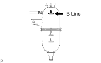
Fill the radiator with TOYOTA Super Long Life Coolant (SLLC) to the reservoir tank's B line.
Standard capacity 9.8 liters (10.4 US qts, 8.6 Imp. qts) Tech Tips
TOYOTA vehicles are filled with TOYOTA SLLC at the factory. In order to avoid damage to the engine cooling system and other technical problems, only use TOYOTA SLLC or similar high quality ethylene glycol based non-silicate, non-amine, non-nitrite, non-borate coolant with long-life hybrid organic acid technology (coolant with long-life hybrid organic acid technology consists of a combination of low phosphates and organic acids).
Note
Never use water as a substitute for engine coolant.
-
Press the inlet and outlet radiator hoses several times by hand, and then check the level of the coolant.
If the coolant level drops below the B line, add TOYOTA SLLC to the B line.
-
Install the radiator reservoir cap.
-

Using a wrench, install the vent plug.
- Torque:
- 2.0 N*m { 20 kgf*cm, 18 in.*lbf }
-
Bleed air from the cooling system.
-
Warm up the engine until the thermostat opens. While the thermostat is open, circulate the coolant for several minutes.
Tech Tips
The thermostat open timing can be confirmed by pressing the inlet radiator hose by hand, and checking when the engine coolant starts to flow inside the hose.
-
Maintain the engine speed at 2500 to 3000 rpm.
-
Press the inlet and outlet radiator hoses several times by hand to bleed air.
CAUTION:
When pressing the radiator hoses:
-
Wear protective gloves.
-
Be careful as the radiator hoses are hot.
-
Keep your hands away from the radiator fan.
-
-
Stop the engine and wait until the coolant cools down to ambient temperature.
CAUTION:
Do not remove the radiator reservoir cap while the engine and radiator are still hot. Pressurized, hot engine coolant and steam may be released and cause serious burns.
-
-
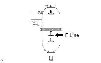
After the coolant cools down, check that the coolant level is at the F line.
If the coolant level is below the F line, add TOYOTA SLLC to the F line.
-
-
BLEED AIR FROM FUEL SYSTEM
-
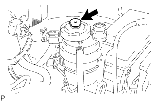
Using the hand pump mounted on the fuel filter cap, bleed the air from the fuel system. Continue pumping until the pump resistance increases.
Note
-
Hand pump pumping speed: Max. 2 strokes/ sec.
-
The hand pump must be pushed with a full stroke during pumping.
-
When the fuel pressure at the supply pump inlet port reaches a saturated pressure, the hand pump resistance increases.
-
If pumping is interrupted during the air bleeding process, fuel in the fuel line may return to the fuel tank. Continue pumping until the hand pump resistance increases.
-
If the hand pump resistance does not increase despite consecutively pumping 200 times or more, there may be a fuel leak between the fuel tank and fuel filter, the hand pump may be malfunctioning, or the vehicle may have run out of fuel.
-
If air bleeding using the hand pump is incomplete, the common rail pressure does not rise to the pressure range necessary for normal use, and the engine cannot be started.
-
-
Start the engine.
Note
-
Even if air bleeding using the hand pump has been completed, the starter may need to be cranked for 10 seconds or more to start the engine.
-
Do not crank the engine continuously for more than 20 seconds. The battery may be discharged.
-
Use a fully-charged battery.
-
When the engine can be started, proceed to the next step.
-
If the engine cannot be started, bleed the air again using the hand pump until the hand pump resistance increases (refer to the procedures above). Then start the engine.
-
-
Turn the ignition switch off.
-
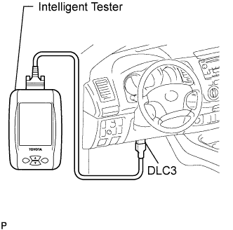
Connect the intelligent tester to the DLC3.
-
Turn the ignition switch to ON and turn the intelligent tester on.
-
Clear the DTCs Click here.
-
Start the engine.*1
-
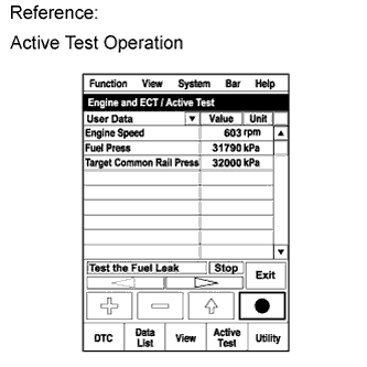
Enter the following menus: Powertrain / Engine and ECT / Active Test / Test the Fuel Leak.*2
-
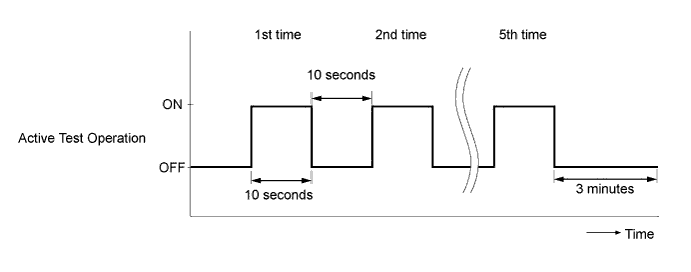
Perform the following test 5 times with on/off intervals of 10 seconds: Active Test / Test the Fuel Leak.*3
-
Allow the engine to idle for 3 minutes or more after performing the Active Test for the fifth time.
Tech Tips
When the Active Test "Test the Fuel Leak" is used to change the pump control mode, the actual fuel pressure inside the common rail drops below the target fuel pressure when the Active Test is off, but this is normal and does not indicate a pump malfunction.
-
Enter the following menus: Powertrain / Engine and ECT / DTC.
-
Read Current DTCs.
-
Clear the DTCs Click here.
Tech Tips
It is necessary to clear the DTCs as DTC P1604 or P1605 may be stored when air is bled from the fuel system after replacing or repairing fuel system parts.
-
Repeat steps *1 to *3.
-
Enter the following menus: Powertrain / Engine and ECT / DTC.
-
Read Current DTCs.
OK No DTCs are output.
-
-
INSPECT FOR COOLANT LEAK
Note
Do not remove the radiator reservoir cap while the engine and radiator are still hot. Pressurized, hot engine coolant and steam may be released and cause serious burns.
-
Fill the radiator with coolant and attach a radiator cap tester to the radiator reservoir.
-
Warm up the engine.
-
Using the radiator cap tester, increase the pressure inside the radiator to 118 kPa (1.2 kgf/cm2,17.1 psi), and check that the pressure does not drop.
If the pressure drops, check the hoses, radiator and water pump for leaks.
If no external leaks are found, check the cylinder block and head.
-
-
INSPECT FOR OIL LEAK
-
INSPECT FOR FUEL LEAK
CAUTION:
-
During Active Test mode, engine speed becomes high and combustion noise becomes loud, so pay attention.
-
During Active Test mode, fuel becomes high-pressured. Be extremely careful not to expose your eyes, hands, or body to escaped fuel.
-
Check that there are no leaks from any part of the fuel system when the engine is stopped.
If there is fuel leakage, repair or replace parts as necessary.
-
Start the engine and check that there are no leaks from any part of the fuel system.
If there is fuel leakage, repair or replace parts as necessary.
-
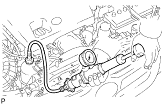
Disconnect the return hose from the common rail.
-
Start the engine and check for fuel leaks from the return pipe.
If there is fuel leakage, replace the common rail.
-
Connect the intelligent tester to the DLC3.
-
Start the engine and push the intelligent tester main switch ON.
-
Select the Fuel Leak test from the Active Test mode on the intelligent tester.
-
If the intelligent tester is not available, fully depress the accelerator pedal quickly. Increase the engine speed to the maximum and maintain that speed for 2 seconds. Repeat this operation several times.
-
Check that there are no leaks from any part of the fuel system.
Note
A return pipe leakage of less than 10 cc (0.6 cu in.) per minute is acceptable.
If there is fuel leakage, repair or replace parts as necessary.
-
Reconnect the return hose to the common rail.
-
-
INSPECT ENGINE OIL LEVEL
-
Warm up the engine, stop the engine and wait 5 minutes. The oil level should be between the dipstick's low and full level marks.
If the oil level is low, check for leakage and add oil up to the full level mark.
Note
Do not fill engine oil above the full level mark.
-
-
INSTALL NO. 1 ENGINE UNDER COVER SUB-ASSEMBLY
- Torque:
- 28 N*m { 286 kgf*cm, 21 ft.*lbf }