CAMSHAFT REMOVAL

CAUTION / NOTICE / HINT
The necessary procedures (adjustment, calibration, initialization, or registration) that must be performed after parts are removed and installed, or replaced during camshaft removal/installation are shown below.
| Replaced Part or Performed Procedure | Necessary Procedure | Effect/Inoperative Function when Necessary Procedure not Performed | Link |
|---|---|---|---|
| Battery terminal is disconnected/reconnected | Perform steering sensor zero point calibration | Lane departure alert system (w/ Steering Control) | |
| Pre-collision system | |||
| Memorize steering angle neutral point | Parking assist monitor system | ||
| Panoramic view monitor system | |||
|
Inspection after repair |
|
PROCEDURE
-
PRECAUTION
Note
After turning the engine switch off, waiting time may be required before disconnecting the cable from the negative (-) battery terminal. Therefore, make sure to read the disconnecting the cable from the negative (-) battery terminal notices before proceeding with work.
-
DISCONNECT CABLE FROM NEGATIVE BATTERY TERMINAL
Note
When disconnecting the cable, some systems need to be initialized after the cable is reconnected.
-
REMOVE FRONT WHEEL RH
-
REMOVE FRONT FENDER APRON SEAL RH
-
REMOVE COOL AIR INTAKE DUCT SEAL
-
REMOVE NO. 1 ENGINE COVER SUB-ASSEMBLY
-
REMOVE INLET AIR CLEANER ASSEMBLY
-
REMOVE AIR CLEANER ASSEMBLY WITH AIR CLEANER HOSE
-
DISCONNECT HOSES
-
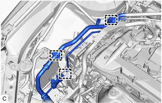
Disengage the 3 clamps.
-
-
REMOVE FUEL HOSE BRACKET
-

Disengage the 2 clamps to disconnect the 2 fuel hoses.
-
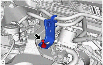
Remove the engine cover joint and fuel hose bracket from the EGR valve bracket.
-
-
REMOVE FUEL PUMP WITH SEAL SUB-ASSEMBLY (for High Pressure)
-
DISCONNECT ENGINE WIRE
-
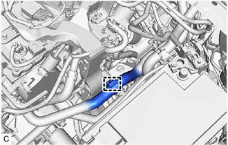
Disengage the clamp.
-
Disconnect the connectors and disengage the clamps.
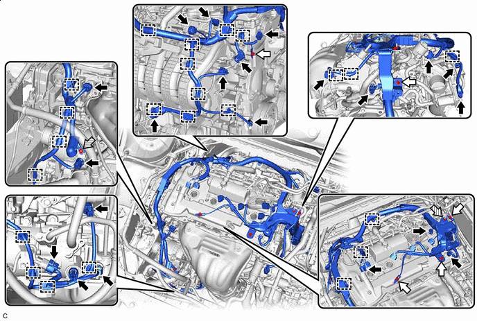

Bolt 
Nut -
Remove the bolts and nuts and disconnect the engine wire from the engine.
-
-
REMOVE VACUUM PUMP ASSEMBLY
-
REMOVE IGNITION COIL ASSEMBLY
-
DISCONNECT NO. 2 VENTILATION HOSE
-
REMOVE CYLINDER HEAD COVER SUB-ASSEMBLY
-
SET NO. 1 CYLINDER TO TDC/COMPRESSION
-
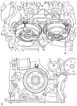
*a Paint Mark *b Timing Mark *c Timing Notch (Groove) Turn the crankshaft pulley until its timing notch (groove) and the timing mark "0" of the timing chain cover sub-assembly are aligned.
-
Check that both timing marks on the camshaft timing gear assembly and camshaft timing exhaust gear assembly are facing upward as shown in the illustration. If not, turn the crankshaft 1 revolution (360°) to align the timing marks as shown in the illustration.
Tech Tips
"A" is not a timing mark.
-
Place paint marks on the chain sub-assembly in alignment with the timing marks on the camshaft timing gear assembly and camshaft timing exhaust gear assembly.
-
-
REMOVE TIMING CHAIN COVER PLATE
-
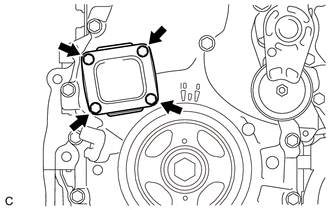
Remove the 4 bolts, timing chain cover plate and gasket.
-
-
REMOVE NO. 1 CHAIN TENSIONER ASSEMBLY
-
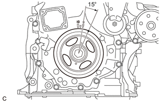
Turn the crankshaft pulley approximately 15° clockwise.
-
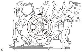
Turn the crankshaft pulley approximately 15° counterclockwise.
-
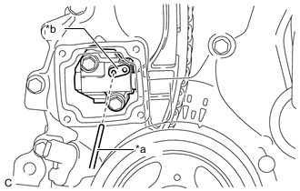
*a Pin *b Stopper Plate Align the holes of the stopper plate and No. 1 chain tensioner assembly, and insert a pin into the stopper plate hole to lock the No. 1 chain tensioner assembly.
-
Turn the crankshaft pulley approximately 15° clockwise.
-
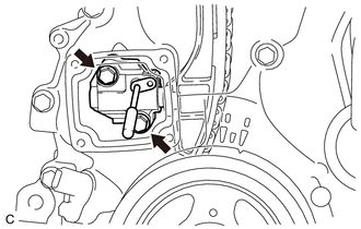
Remove the 2 bolts, No. 1 chain tensioner assembly and gasket.
Note
Make sure not to drop the gasket inside the timing chain cover sub-assembly.
-
Turn the crankshaft pulley approximately 15° counterclockwise.
-
-
REMOVE TIMING CHAIN GUIDE
-
REMOVE CAMSHAFT TIMING OIL CONTROL SOLENOID ASSEMBLY
-
REMOVE CAMSHAFT TIMING GEAR BOLT
-
*a Hold 
Turn Hold the hexagonal portion of the camshaft with a wrench and remove the camshaft timing gear bolt from the camshaft.
Note
Be careful not to damage the cylinder head sub-assembly or spark plug tube with the wrench.
-
-
REMOVE CAMSHAFT BEARING CAP
-
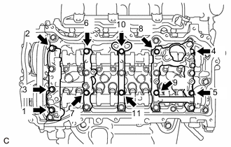
Remove the 11 bolts in several steps in the order shown in the illustration.
-
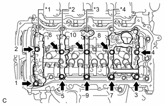
*1 No. 1 Camshaft Bearing Cap *2 No. 2 Camshaft Bearing Cap *3 No. 3 Camshaft Bearing Cap *4 No. 4 Camshaft Bearing Cap Remove the 10 bolts in several steps in the order shown in the illustration.
-
Remove the No. 1 camshaft bearing cap, No. 2 camshaft bearing cap, No. 3 camshaft bearing cap and No. 4 camshaft bearing cap.
Tech Tips
Arrange the removed parts in the correct order.
-
-
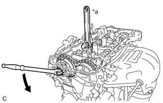
REMOVE CAMSHAFT
-
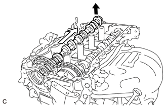
Raise the camshaft as shown in the illustration to remove it from the camshaft timing gear assembly.
Note
Be careful not to damage the camshaft or camshaft timing gear assembly with the wrench.
-
-
REMOVE CAMSHAFT TIMING GEAR ASSEMBLY
-
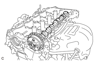
Remove the camshaft timing gear assembly.
Note
-
Do not disassemble the camshaft timing gear assembly.
-
Be careful not to damage the camshaft timing gear assembly.
-
-
-
REMOVE NO. 2 CAMSHAFT
-
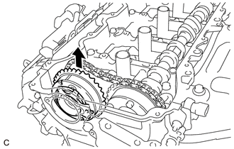
Hold up the chain sub-assembly and remove the No. 2 camshaft from the camshaft housing sub-assembly.
-
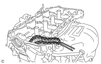
Suspend the chain sub-assembly with a string or equivalent as shown in the illustration.
Note
Be careful not to drop the chain sub-assembly inside the timing chain cover sub-assembly.
-
-
REMOVE CAMSHAFT TIMING EXHAUST GEAR ASSEMBLY
-
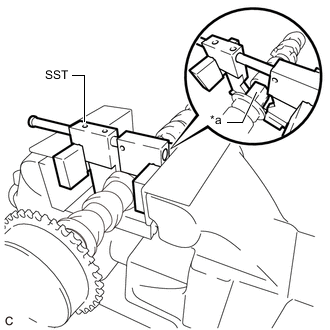
*a Hexagonal Portion Using SST, grip the hexagonal portion, and then secure the SST and No. 2 camshaft in a vise as shown in the illustration.
- SST
- 09212-31010
Note
-
Do not damage the No. 2 camshaft.
-
Never grip areas other than the hexagonal portion, as this may cause damage.
-
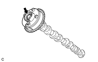
Remove the bolt and camshaft timing exhaust gear assembly.
Note
Do not disassemble the camshaft timing exhaust gear assembly.
-
-
REMOVE OIL CONTROL VALVE FILTER
-
REMOVE NO. 1 CAMSHAFT BEARING
-
REMOVE NO. 2 CAMSHAFT BEARING