ENGINE UNIT REASSEMBLY

PROCEDURE
-
INSTALL STIFFENING CRANKCASE RING PIN
Note
It is not necessary to remove ring pins unless they are being replaced.
-
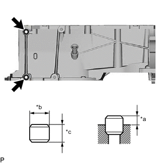
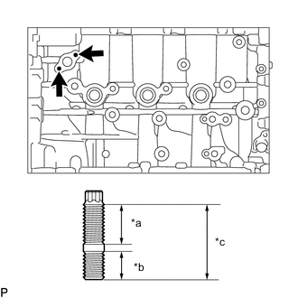
*a Protrusion Height *b 11 mm *c 8 mm Using a plastic hammer, tap 2 new ring pins into the stiffening crankcase assembly.
Standard Ring Pin Item Protrusion Height Height Width Ring pin 4.0 mm (0.157 in.) 8.0 mm (0.315 in.) 11 mm (0.433 in.) -
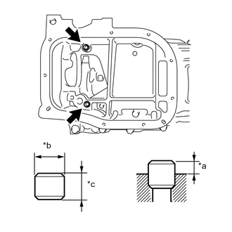
*a Protrusion Height *b 11 mm (0.433 in.) *c 8 mm (0.315 in.) Using a plastic hammer, tap in 2 new stiffening crankcase ring pins until they are seated.
Standard Ring Pin Item Protrusion Height Height Width Stiffening crankcase ring pin 3.0 mm (0.118 in.) 8 mm (0.315 in.) 11 mm (0.433 in.)
-
-
INSTALL STUD BOLT
Note
If a stud bolt is deformed or the threads are damaged, replace it.
-
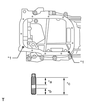
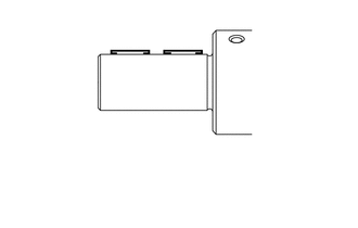
*1 Stud Bolt *a 8.5 mm (0.335 in.) *b 8.0 mm (0.315 in.) *c 18 mm (0.709 in.) Using an E6 "TORX" socket wrench, install the stud bolts as shown in the illustration.
- Torque:
- 5.0 N*m { 51 kgf*cm, 44 in.*lbf }
-
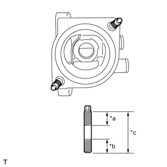
*a 15 mm (0.591 in.) *b 12 mm (0.472 in.) *c 34 mm (1.339 in.) Using an E6 "TORX" socket wrench, install the stud bolts as shown in the illustration.
- Torque:
- 5.0 N*m { 51 kgf*cm, 44 in.*lbf }
-
*a 12 mm (0.472 in.) *b 9.0 mm (0.354 in.) *c 23 mm (0.906 in.) Using an E5 "TORX" socket wrench, install the stud bolts as shown in the illustration.
- Torque:
- 5.0 N*m { 51 kgf*cm, 44 in.*lbf }
-
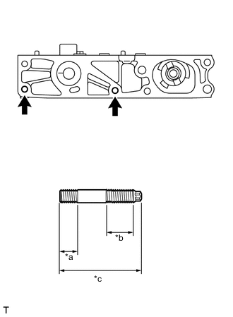
*a 12 mm (0.472 in.) *b 18 mm (0.709 in.) *c 48.5 mm (1.909 in.) Using an E7 "TORX" socket wrench, install the camshaft housing stud bolts.
- Torque:
- 9.5 N*m { 97 kgf*cm, 84 in.*lbf }
-
-
INSTALL STIFFENING CRANKCASE ASSEMBLY
-
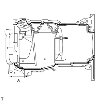
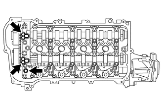
Apply seal packing in a continuous line as shown in the illustration.
Seal Packing Toyota Genuine Seal Packing Black, Three Bond 1207B or equivalent Standard Seal Diameter Area Specified Condition Continuous Line 2.0 to 3.0 mm (0.0787 to 0.118 in.) A 4.5 to 5.5 mm (0.177 to 0.217 in.) Application Length (A) 56 mm (2.20 in.) Note
-
Remove any oil from the contact surfaces.
-
Install the stiffening crankcase assembly within 3 minutes and tighten the bolts within 15 minutes of applying seal packing.
-
Do not start the engine for at least 2 hours after installing the stiffening crankcase assembly.
-
-
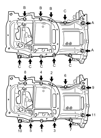
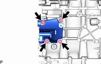
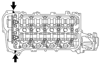
Install the stiffening crankcase assembly with the 11 bolts in the order shown in the illustration.
- Torque:
- 21 N*m { 214 kgf*cm, 15 ft.*lbf }
Bolt Length Item Specified Condition Bolt (A) 143.7 mm (5.43 in.) Bolt (B) 35 mm (1.38 in.) Bolt (C) 70 mm (2.76 in.) -
Recheck the torque for the bolts (1) and (2).
- Torque:
- 21 N*m { 214 kgf*cm, 15 ft.*lbf }
-
Wipe off any excess seal packing with a clean piece of cloth.
-
-
INSTALL OIL PUMP ASSEMBLY
-
INSTALL NO. 2 OIL PAN SUB-ASSEMBLY
-
INSTALL OIL PAN DRAIN PLUG
-
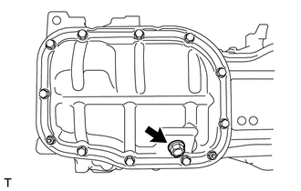
Install a new gasket and oil pan drain plug to the No. 2 oil pan sub-assembly.
- Torque:
- 37 N*m { 377 kgf*cm, 27 ft.*lbf }
-
-
INSTALL REAR ENGINE OIL SEAL
-
INSTALL NO. 1 TAPER SCREW PLUG
-
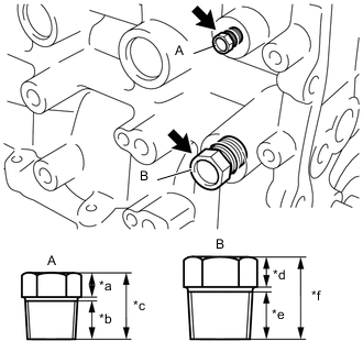
*a 5.0 mm (0.197 in.) *b 11 mm (0.433 in.) *c 18 mm (0.709 in.) *d 8.0 mm (0.315 in.) *e 12.5 mm (0.492 in.) *f 22 mm (0.866 in.) Apply adhesive to 2 or 3 threads of the No. 1 taper screw plug, and install the No. 1 taper screw plug (A).
- Torque:
- 25 N*m { 255 kgf*cm, 18 ft.*lbf }
Adhesive Toyota Genuine Adhesive 1344, Three Bond 1344 or equivalent Note
-
Install the No. 1 taper screw plug within 3 minutes of applying adhesive.
-
Do not start the engine for at least 1 hour after installing the No. 1 taper screw plug.
-
Apply adhesive to 2 or 3 threads of the No. 1 taper screw plug, and install the No. 1 taper screw plug (B).
- Torque:
- 43 N*m { 438 kgf*cm, 32 ft.*lbf }
Adhesive Toyota Genuine Adhesive 1324, Three Bond 1324 or equivalent Note
-
Install the No. 1 taper screw plug within 3 minutes of applying adhesive.
-
Do not start the engine for at least 1 hour after installing the No. 1 taper screw plug.
-
-
INSTALL PCV VALVE (VENTILATION VALVE SUB-ASSEMBLY)
-
INSTALL CYLINDER HEAD GASKET
-
INSTALL CYLINDER HEAD SUB-ASSEMBLY
-
INSTALL VALVE STEM CAP
-
Apply a light coat of engine oil to the valve stem ends.
-
Install the 16 valve stem caps to the valve stems.
Tech Tips
Do not drop the valve stem caps into the cylinder head sub-assembly.
-
-
INSTALL VALVE LASH ADJUSTER ASSEMBLY
-
Inspect each valve lash adjuster assembly before installing it.
-
Install the 16 valve lash adjuster assemblies to the cylinder head sub-assembly.
Note
Install the valve lash adjuster assembly to the same place it was removed from.
-
-
INSTALL NO. 1 VALVE ROCKER ARM SUB-ASSEMBLY
-
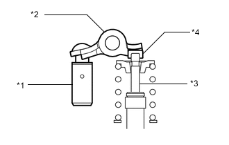
*1 Valve Lash Adjuster Assembly *2 No. 1 Valve Rocker Arm Sub-assembly *3 Valve Stem *4 Valve Stem Cap Apply engine oil to the valve lash adjuster assembly tips and valve stem cap ends.
-
Make sure that the No. 1 valve rocker arm sub-assemblies are installed as shown in the illustration.
-
-
INSTALL CAMSHAFT HOUSING STRAIGHT PIN
Note
It is not necessary to remove a camshaft housing straight pin unless it is being replaced.
-
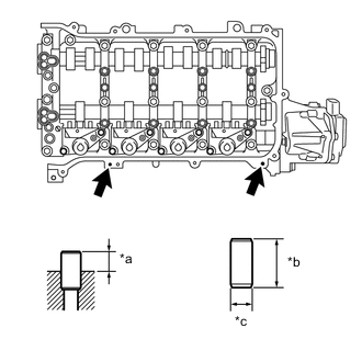
*a Protrusion Height *b 14 mm (0.551 in.) *c 6.0 mm (0.236 in.) Using a plastic hammer, tap in a new camshaft housing straight pin to the specified protrusion height.
Standard Straight Pin Item Protrusion Height Height Width Camshaft housing straight pin 6.5 to 7.5 mm (0.256 to 0.295 in.) 14 mm (0.551 in.) 6.0 mm (0.236 in.)
-
-
INSTALL CONTINUOUSLY VARIABLE VALVE LIFT CONTROLLER ASSEMBLY
-
INSTALL CAMSHAFT HOUSING SUB-ASSEMBLY
-
INSTALL CAMSHAFT TIMING GEAR ASSEMBLY
-
INSTALL CAMSHAFT TIMING EXHAUST GEAR ASSEMBLY
-
INSTALL CRANKSHAFT TIMING GEAR KEY
-
Using a plastic hammer, tap in the 2 crankshaft timing gear keys.
Tech Tips
Tap in the crankshaft timing gear keys until they contact the crankshaft as shown in the illustration.
-
-
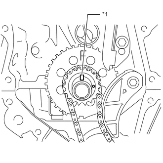
INSTALL NO. 1 CRANKSHAFT POSITION SENSOR PLATE
-
Install the No. 1 crankshaft position sensor plate with the "F" mark facing forward.
-
-
INSTALL NO. 2 CHAIN SUB-ASSEMBLY
-
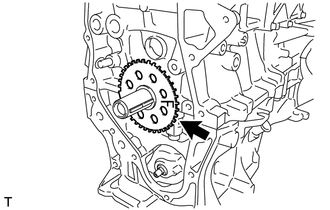
INSTALL CRANKSHAFT TIMING SPROCKET
-
INSTALL NO. 1 CHAIN VIBRATION DAMPER
-
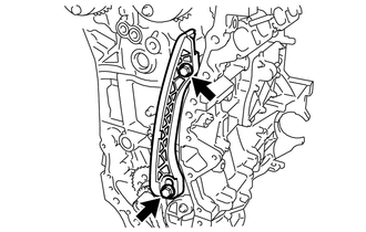
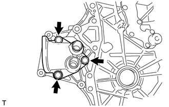
Install the No. 1 chain vibration damper with the 2 bolts.
- Torque:
- 21 N*m { 214 kgf*cm, 15 ft.*lbf }
-
-
SET NO. 1 CYLINDER TO TDC/COMPRESSION
-
Temporarily install the crankshaft pulley bolt.
-
*1 Timing Gear Key Turn the crankshaft counterclockwise to position the timing gear key to the top.
-
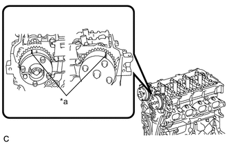
*a Timing Mark Check that the timing marks on the camshaft timing exhaust gear assembly and camshaft timing gear assembly are aligned as shown in the illustration.
-
Remove the crankshaft pulley bolt.
-
-
INSTALL CHAIN SUB-ASSEMBLY
-
Align the mark plates (orange) with the timing marks as shown in the illustration and install the chain sub-assembly.
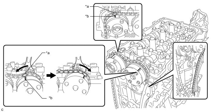
*a Mark Plate (Orange) *b Timing Mark Tech Tips
-
Be sure to position the mark plate at the front of the engine.
-
The mark plate on the camshaft side is colored orange.
-
Do not pass the chain sub-assembly around the sprocket of the camshaft timing gear assembly. Only place it on the sprocket.
-
Pass the chain sub-assembly through the No. 1 chain vibration damper.
-
-
Hold the hexagonal portion of the camshaft with a wrench and turn the camshaft timing gear assembly counterclockwise to align the mark plate (orange) and timing mark, and then install the chain sub-assembly.
-
Hold the hexagonal portion of the camshaft with a wrench and turn the camshaft timing gear assembly clockwise.
Tech Tips
To tension the chain sub-assembly, slowly turn the camshaft timing gear assembly clockwise to prevent the chain sub-assembly from being misaligned.
-
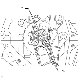
*a Timing Mark *b Mark Plate (Pink) Align the mark plates (pink) and timing marks and install the chain to the crankshaft timing gear.
Tech Tips
The mark plates on the crankshaft side are colored pink.
-
-
INSTALL CHAIN TENSIONER SLIPPER
-
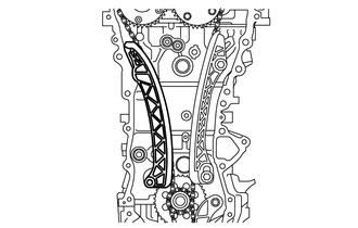
Install the chain tensioner slipper to the cylinder block sub-assembly.
-
-
CHECK NO. 1 CYLINDER TO TDC/COMPRESSION
-
Check each timing mark at TDC/compression.
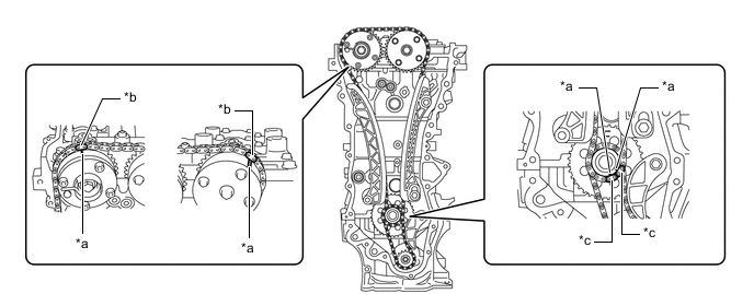
*a Timing Mark *b Mark Plate (Orange) *c Mark Plate (Pink) - -
-
-
INSTALL NO. 1 GENERATOR BRACKET
-
Install the No. 1 generator bracket with the 4 bolts.
- Torque:
- 24 N*m { 245 kgf*cm, 18 ft.*lbf }
-
-
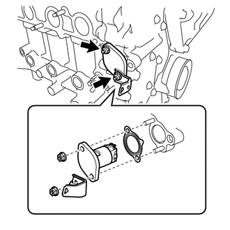
INSTALL WATER INLET HOUSING
-
Install a new gasket and the water inlet housing with the 3 bolts.
- Torque:
- 10 N*m { 102 kgf*cm, 7 ft.*lbf }
-
-
INSTALL TIMING CHAIN COVER SUB-ASSEMBLY
-
INSTALL TIMING CHAIN COVER OIL SEAL
-
INSTALL CRANKSHAFT PULLEY
-
INSTALL NO. 1 CHAIN TENSIONER ASSEMBLY
-
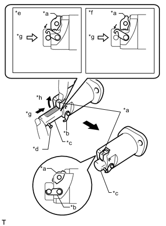
*a Cam *b Hook *c Plunger *d Pin *e Correct *f Incorrect *g Push *h Raise Raise the cam, then fully push in the plunger and engage the hook to the pin so that the plunger is in the position shown in the illustration.
Note
Make sure that the cam engages the first tooth of the plunger to allow the hook to pass over the pin.
-
Install a new gasket, the bracket and No. 1 chain tensioner assembly with the 2 nuts.
- Torque:
- 12 N*m { 122 kgf*cm, 9 ft.*lbf }
Note
If the hook releases the plunger while the No. 1 chain tensioner assembly is being installed, set the hook again.
-
*a Hook *b Disconnect Rotate the crankshaft counterclockwise slightly and check that the hook is released.
-
*a Plunger *b Plunger Extended Turn the crankshaft clockwise and check that the plunger is extended.
-
-
INSTALL OIL FILTER BRACKET CLIP (for Oil Filter Element Kit Type)
-
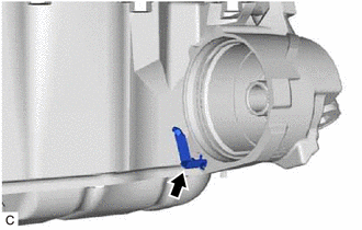
Install the oil filter bracket clip to the oil filter bracket.
-
-
INSTALL OIL FILTER UNION (for Oil Filter Sub-assembly Type)
-
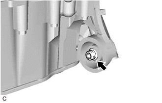
Using a 12 mm hexagon socket wrench, install the oil filter union to the oil filter bracket.
- Torque:
- 29.5 N*m { 301 kgf*cm, 22 ft.*lbf }
-
-
INSTALL OIL FILTER
-
INSTALL SPARK PLUG TUBE GASKET
-
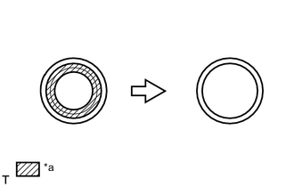
*a Part to Cut Off Using a cutter knife, cut off the seal part of the removed spark plug tube gasket.
-
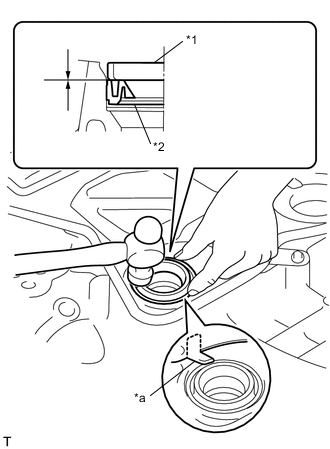
*a Claw *1 Spark Plug Tube Gasket without Seal Part *2 New Spark Plug Tube Gasket Using a hammer and the spark plug tube gasket which has had the sealing part cut off, uniformly tap in a new spark plug tube gasket all the way.
Note
-
Keep the lip free from foreign matter.
-
Do not tap the spark plug tube gasket.
Tech Tips
If a spark plug tube gasket that will be used to install the spark plug tube gasket is deformed, and cannot be positioned on the spark plug tube gasket, correct the deformation using pliers.
-
-
Return the claws of the ventilation baffle plate to their original positions.
-
-
INSTALL CYLINDER HEAD COVER GASKET
-
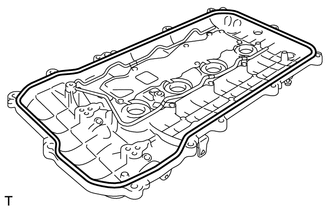
Install a new cylinder head cover gasket to the cylinder head cover sub-assembly.
Note
Remove any oil from the contact surfaces.
-
-
INSTALL CYLINDER HEAD COVER SUB-ASSEMBLY
-
Install 3 new gaskets to the camshaft bearing cap.
-
Apply seal packing as shown the illustration.
Seal Packing Toyota Genuine Seal Packing Black, Three Bond 1207B or equivalent Standard Diameter 4.0 mm (0.157 in.) Note
-
Remove any oil from the contact surfaces.
-
Install the cylinder head cover sub-assembly within 3 minutes and tighten the bolts within 15 minutes of applying seal packing.
-
Do not start the engine for at least 2 hours after installation.
-
-
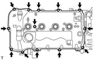
Install the cylinder head cover sub-assembly with a new seal washer and the 13 bolts.
- Torque:
- 10 N*m { 102 kgf*cm, 7 ft.*lbf }
-
-
INSTALL ENGINE OIL PRESSURE SWITCH ASSEMBLY
-
INSTALL ENGINE COOLANT TEMPERATURE SENSOR
-
INSTALL KNOCK SENSOR
-
INSTALL CRANKSHAFT POSITION SENSOR
-
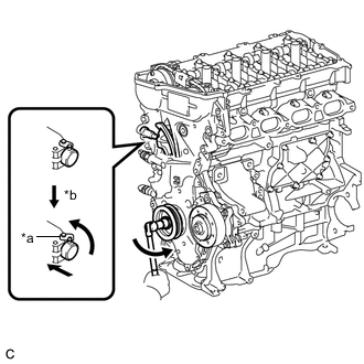
INSTALL CAMSHAFT TIMING OIL CONTROL VALVE ASSEMBLY
-
for Intake Side:
-
for Exhaust Side:
-
-
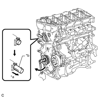
INSTALL CAMSHAFT POSITION SENSOR
-
for Intake Side:
-
for Exhaust Side:
-
-
INSTALL SPARK PLUG
-
INSTALL ENGINE COVER JOINT
-
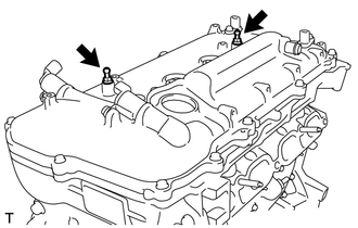
Install the 2 engine cover joints.
- Torque:
- 10 N*m { 102 kgf*cm, 7 ft.*lbf }
-
-
INSTALL OIL FILLER CAP GASKET
-
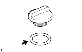
Install the oil filler cap gasket to the oil filler cap sub-assembly.
-
-
INSTALL OIL FILLER CAP SUB-ASSEMBLY
-
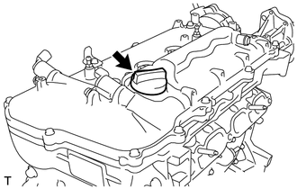
Install the oil filler cap sub-assembly.
-