STEERING GEAR INSTALLATION

PROCEDURE
-
INSTALL TIE ROD END SUB-ASSEMBLY LH
-
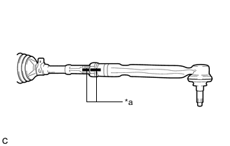
*a Matchmark Install the lock nut and tie rod end sub-assembly LH to the steering gear assembly until the matchmarks are aligned.
Tech Tips
After adjusting the toe-in, tighten the lock nut.
-
-
INSTALL TIE ROD END SUB-ASSEMBLY RH
Tech Tips
Perform the same procedure as for the LH side.
-
INSTALL STEERING LINK ASSEMBLY
-
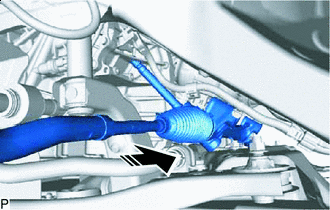

Install in this Direction Insert the steering link assembly as shown in the illustration.
-
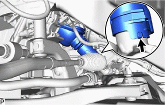
Align the protrusion of the steering link assembly with the hole of the No. 1 steering column hole cover sub-assembly, and install the No. 1 steering column hole cover sub-assembly to the steering link assembly.
Tech Tips
Check that the No. 1 steering column hole cover sub-assembly is securely installed.
-
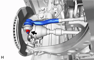
Install the steering link assembly to the front suspension crossmember sub-assembly with the 2 bolts and 2 new nuts.
- Torque:
- 133 N*m { 1356 kgf*cm, 98 ft.*lbf }
Note
-
Because the nut has its own stopper, do not turn the nut. Tighten the bolt with the nut secured.
-
Make sure to tighten the bolts starting from the left side of the vehicle.
-
for AWD:
-
Install the wire harness clamp bracket to the front suspension crossmember sub-assembly with the bolt.
-
Engage the clamp and Connect the connector.
-
-
for 2WD:
-
Install the wire harness clamp bracket to the front suspension crossmember sub-assembly with the bolt.
-
Connect the connector.
-
-
-
CONNECT TIE ROD END SUB-ASSEMBLY LH
-
Connect the tie rod end sub-assembly LH to the steering knuckle LH with the nut.
- Torque:
- 49 N*m { 500 kgf*cm, 36 ft.*lbf }
Note
-
Do not damage the ball joint dust cover.
-
Further tighten the nut up to 60° if the holes for the cotter pin are not aligned.
-
Install a new cotter pin.
-
-
CONNECT TIE ROD END SUB-ASSEMBLY RH
Tech Tips
Perform the same procedure as for the LH side.
-
CONNECT NO. 1 STEERING COLUMN HOLE COVER SUB-ASSEMBLY
-
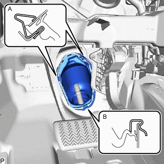
Engage the clip (B) to the vehicle body.
-
Engage the clip (A) to install the No. 1 steering column hole cover sub-assembly to the vehicle body.
Note
Be careful not to damage the lip of the No. 1 steering column hole cover sub-assembly.
-
-
CONNECT NO. 2 STEERING INTERMEDIATE SHAFT ASSEMBLY
-
INSTALL COLUMN HOLE COVER SILENCER SHEET
-
INSTALL FRONT WHEELS
-
STABILIZE SUSPENSION
-
INSPECT AND ADJUST FRONT WHEEL ALIGNMENT