SFI SYSTEM (w/ Dual VVT-i), Diagnostic DTC:P1550, P1551, P1552
| DTC Code | DTC Name |
|---|---|
| P1550 | Battery Current Sensor Circuit |
| P1551 | Battery Current Sensor Circuit Low |
| P1552 | Battery Current Sensor Circuit High |
DESCRIPTION
The battery current sensor assembly detects the battery charge and discharge current amount. The battery current sensor assembly changes this information into a voltage signal and outputs it to the ECM. Based on this signal, the ECM sends power generation voltage commands to the generator.
| DTC Code | DTC Detection Condition | Trouble Area |
|---|---|---|
| P1550 | When the ignition switch is ON, the difference between the maximum and minimum current values is less than 1 A for 10 seconds or more (1 trip detection logic). |
|
| P1551 | When the ignition switch is ON, the battery current sensor output is less than 0.2 V for 0.5 seconds or more (1 trip detection logic). |
|
| P1552 | When the ignition switch is ON, the battery current sensor output is higher than 4.8 V for 0.5 seconds or more (1 trip detection logic). |
|
MONITOR STRATEGY
| Frequency of operation | Continuous |
CONFIRMATION DRIVING PATTERN
-
Connect the GTS to the DLC3.
-
Turn the ignition switch to ON and turn the GTS on.
-
Clear the DTCs (even if no DTCs are stored, perform the clear DTC operation).
-
Turn the ignition switch off and wait for at least 30 seconds.
-
Turn the ignition switch to ON and turn the GTS on.
-
Wait for 10 seconds or more.
-
Enter the following menus: Powertrain / Engine and ECT / Trouble Code.
-
Read Pending DTCs.
Tech Tips
-
If a pending DTC is output, the system is malfunctioning.
-
If a pending DTC is not output, perform the following procedure.
-
-
Enter the following menus: Powertrain / Engine and ECT / Utility / All Readiness.
-
Input the DTC: P1550, P1551 or P1552.
-
Check the DTC judgment result.
GTS Display Description NORMAL
-
DTC judgment completed
-
System normal
ABNORMAL
-
DTC judgment completed
-
System abnormal
INCOMPLETE
-
DTC judgment not completed
-
Perform driving pattern after confirming DTC enabling conditions
N/A
-
Unable to perform DTC judgment
-
Number of DTCs which do not fulfill DTC preconditions has reached ECU memory limit
Tech Tips
-
If the judgment result shows NORMAL, the system is normal.
-
If the judgment result shows ABNORMAL, the system has a malfunction.
-
If the judgment result shows INCOMPLETE or N/A, perform the Confirmation Driving Pattern and check the DTC judgment result again.
-
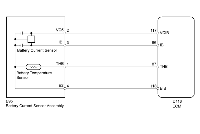
WIRING DIAGRAM
INSPECTION PROCEDURE
PROCEDURE
-
CHECK FOR DTC
-
Connect the GTS to the DLC3.
-
Turn the ignition switch to ON.
-
Turn the GTS on.
-
According to the display on the GTS, check for DTCs Click here.
Result Result Proceed to DTC P1550, P1551 or P1552 is output. A DTCs other than P1550, P1551 and P1552 are output. B
B 
GO TO DTC CHART Click here
A 
-
-
READ VALUE USING GTS (BATTERY CURRENT)
-
Connect the GTS to the DLC3.
-
Turn the ignition switch to ON and turn off all electrical devices (headlights, blower motor, wiper, rear defogger, etc.).
-
Turn the GTS on.
-
Select the item below in the Data List, and read the display on the GTS Click here.
Result Result Proceed to Current value displayed on GTS is fixed at 0 A and does not change, or only changes by 1 A or less between -98 and 98 A. A Current value displayed on GTS changes between -20 and 0 A. B
B
CHECK FOR INTERMITTENT PROBLEMS Click here
A
-
-
INSPECT BATTERY CURRENT SENSOR ASSEMBLY
-
Inspect the battery current sensor assembly Click here.
NG
REPLACE BATTERY CURRENT SENSOR ASSEMBLY
OK
-
-
CHECK HARNESS AND CONNECTOR (ECM - BATTERY CURRENT SENSOR)
-
Disconnect the ECM connector.
-
Disconnect the battery current sensor connector.
-
Measure the resistance according to the value(s) in the table below.
Standard Resistance Tester Connection Condition Specified Condition D116-117 (VCIB) - B95-2 (VC5) Always Below 1 Ω D116-118 (EIB) - B95-4 (E2) Always Below 1 Ω D116-86 (IB) - B95-3 (IB) Always Below 1 Ω D116-117 (VCIB) or B95-2 (VC5) - Body ground Always 10 kΩ or higher D116-86 (IB) or B95-3 (IB) - Body ground Always 10 kΩ or higher
NG
REPAIR OR REPLACE HARNESS OR CONNECTOR
OK 
REPLACE ECM Click here
-