FUEL SYSTEM
-
OUTLINE
-
The FA20 engine uses a Direct injection 4-stroke gasoline engine Superior version (D-4S) system, which has both direct and port type fuel injection.
-
This system optimally controls the fuel injectors for direct injection and port injection in accordance with engine load. The system achieves improved engine performance, fuel economy, and clean emissions.
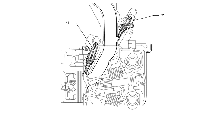
Text in Illustration *1 Fuel Injector Assembly (for Direct Injection) *2 Fuel Injector Assembly (for Port Injection) -
A fuel returnless system is used to reduce evaporative emissions.
-
A fuel cut control is used to stop the fuel pump assembly (for low pressure) if the SRS airbag is deployed.
-
Fuel injector assembly (for direct injection) with slit nozzle is used.
-
-
MAIN FEATURES
-
D-4S System
-
The Direct injection 4-stroke gasoline engine Superior version (D-4S) system is based on 2 types of fuel injection systems: the direct injection system and the port injection system. Fuel sent from the fuel tank assembly is delivered to the low-pressure and high-pressure fuel systems. The fuel delivered to the low-pressure fuel system is injected from the fuel injector assembly (for port injection) to the intake port. The fuel delivered to the high-pressure fuel system is pressurized by the fuel pump assembly (for high pressure) and injected from the fuel injector assembly (for direct injection) to the combustion chamber.
-
The direct injection system mainly consists of the fuel pump assembly (for high pressure), fuel delivery pipe (for direct injection) and fuel injector assembly (for direct injection). In this system, the ECM controls the fuel pump assembly (for high pressure) and fuel injector assembly (for direct injection) via the Electronic Driver Unit (EDU) based on signals from various sensors, thus optimally controlling fuel pressure, injection volume, and injection timing.
-
The port injection system mainly consists of the fuel suction tube with pump and gage assembly (for low pressure), fuel pipe sub-assembly (for port injection), and fuel injector assembly (for port injection). In this system, the ECM controls the fuel injector assembly (for port injection) based on signals from various sensors, thus optimally controlling injection volume and timing.
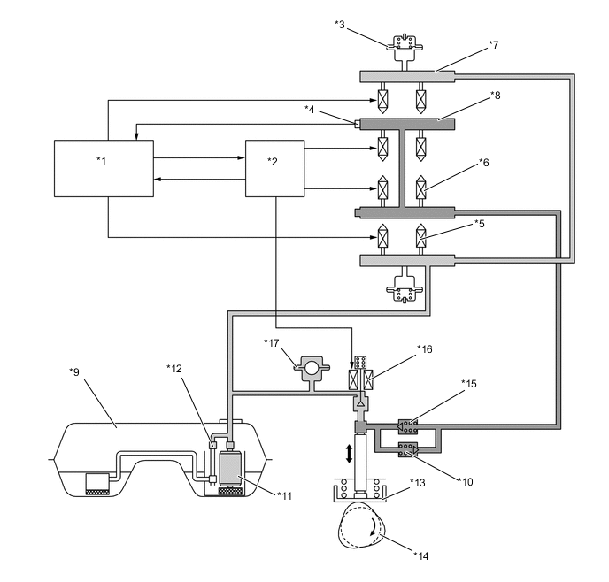
Text in Illustration *1 ECM *2 Injector Driver (EDU) *3 Fuel Pressure Pulsation Damper Assembly *4 Fuel Pressure Sensor *5 Fuel Injector Assembly (for Port Injection) *6 Fuel Injector Assembly (for Direct Injection) *7 Fuel Pipe Sub-assembly (for Port Injection) *8 Fuel Delivery Pipe (for Direct Injection) *9 Fuel Tank Assembly *10 Fuel Relief Valve (for High Pressure) *11 Fuel Suction Tube with Pump and Gage Assembly (for Low Pressure) *12 Fuel Pressure Regulator Assembly *13 Fuel Pump Assembly (for High Pressure) *14 Intake Camshaft (Cam to Drive Fuel Pump) *15 Check Valve *16 Spill Control Valve *17 Pulsation Damper - - 
Low-pressure Fuel 
High-pressure Fuel
-
-
Fuel Returnless System (for Low-pressure Side)
-
A fuel returnless system is used to reduce evaporative emissions. As shown below, by integrating the fuel filter assembly, fuel pressure regulator assembly and fuel pump, it is possible to discontinue the return of fuel from the engine area, thus preventing temperature rise inside the fuel tank assembly. This reduces the generation of evaporative emissions in the fuel tank assembly.
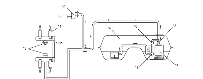
Text in Illustration *1 Fuel Injector Assembly (for Port Injection) *2 Fuel Delivery Pipe Sub-assembly (for Port Injection) *3 Fuel Pressure Pulsation Damper Assembly *4 Fuel Tank Assembly *5 Fuel Filter Assembly *6 Fuel Pressure Regulator Assembly *7 Fuel Suction Tube with Pump and Gage Assembly (for Low Pressure) *8 Jet Pump *9 Fuel Pump Assembly (for High Pressure) - - *a to High-pressure Fuel System - -
-
-