AUTOMATIC TRANSMISSION SYSTEM (for 1KD-FTV) TCM Power Source Circuit
DESCRIPTION
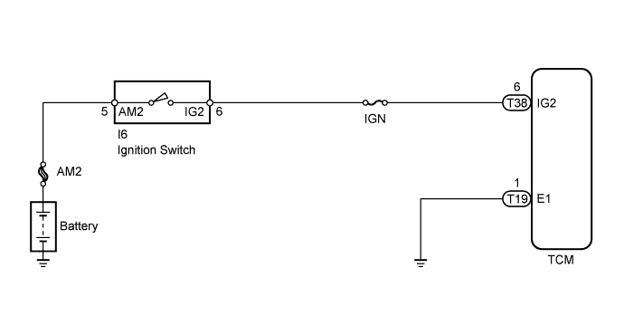
When the ignition switch is turned ON, battery voltage is applied to terminal IG2 of the TCM.
WIRING DIAGRAM
INSPECTION PROCEDURE
PROCEDURE
-
INSPECT FUSE (IGN)
-
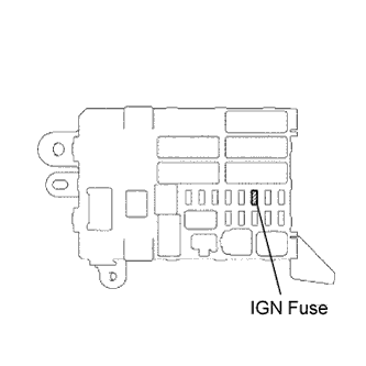
Remove the IGN fuse from the instrument panel junction block.
-
Measure the resistance of the fuse.
Standard Resistance Below 1 Ω
NG 
REPLACE FUSE
OK 
-
-
INSPECT IGNITION SWITCH
-
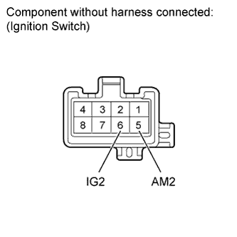
Disconnect the I6 ignition switch connector.
-
Measure the resistance according to the value(s) in the table below.
Standard Resistance Tester Connection Switch Condition Specified Condition 5 (AM2) - 6 (IG2) OFF 10 kΩ or higher 5 (AM2) - 6 (IG2) ON Below 1 Ω
NG
REPLACE IGNITION SWITCH
OK
-
-
CHECK HARNESS AND CONNECTOR (TCM - BODY GROUND)
-
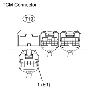
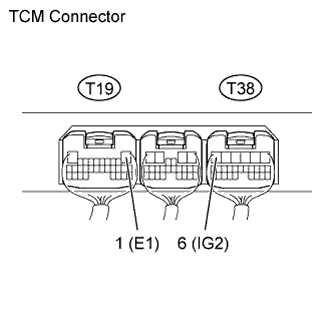
Disconnect the T19 TCM connector.
-
Measure the resistance according to the value(s) in the table below.
Standard Resistance Tester Connection Condition Specified Condition T19-1 (E1) - Body ground Always Below 1 Ω
NG
REPAIR OR REPLACE HARNESS OR CONNECTOR
OK
-
-
CHECK TCM (TCM - BATTERY)
-
Turn the ignition switch to ON.
-
Measure the voltage according to the value(s) in the table below.
Standard Voltage Tester Connection Switch Condition Specified Condition T38-6 (IG2) - T19-1 (E1) Ignition switch ON 11 to 14 V
NG
REPAIR OR REPLACE HARNESS OR CONNECTOR
OK 
REPLACE TCM
-