NAVIGATION SYSTEM(for Sedan) Vehicle Speed Signal Circuit between Radio Receiver and Extension Module
| DTC Code | DTC Name |
|---|---|
| Vehicle Speed Signal Circuit between Radio Receiver and Extension Module |
DESCRIPTION
The navigation ECU receives a vehicle speed signal from the radio and display receiver assembly and information from the navigation antenna assembly, and then adjusts vehicle position.
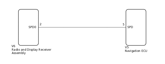
WIRING DIAGRAM
PROCEDURE
CHECK HARNESS AND CONNECTOR (RADIO AND DISPLAY RECEIVER ASSEMBLY - NAVIGATION ECU)
Disconnect the V6 radio and display receiver assembly connector.
Disconnect the V5 navigation ECU connector.
Measure the resistance according to the value(s) in the table below.
Standard Resistance
Tester Connection
Condition
Specified Condition
V6-2 (SPD0) - V5-5 (SPD)
Always
Below 1 Ω
V6-2 (SPD0) - Body ground
Always
10 kΩ or higher
Result
Proceed to
OK
NG
NG REPAIR OR REPLACE HARNESS OR CONNECTOR