CYLINDER BLOCK INSPECTION
PROCEDURE
INSPECT CONNECTING ROD THRUST CLEARANCE
-
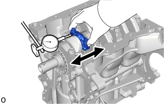
Using a dial indicator, measure the thrust clearance while moving the connecting rod bearing cap back and forth.
Standard Thrust Clearance
0.10 to 0.30 mm (0.00394 to 0.0118 in.)
Maximum Thrust Clearance
0.36 mm (0.0142 in.)
Tip:If the thrust clearance is greater than the maximum, replace the connecting rod sub-assembly. If necessary, replace the crankshaft.
-
INSPECT CONNECTING ROD OIL CLEARANCE
Remove the 2 connecting rod bolts, connecting rod bearing cap and connecting rod bearing.
Clean the crank pin and connecting rod bearing.
Check the crank pin and connecting rod bearing for pitting and scratches.
-
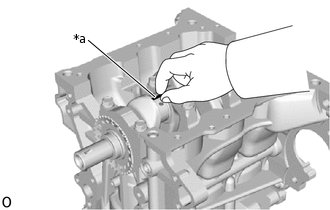
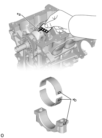
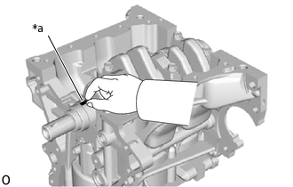
*a
Plastigage
Lay a strip of Plastigage across the crank pin.
-
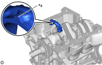
*a
Front Mark
Check that the front mark of the connecting rod bearing cap is facing forward and install the connecting rod bearing cap.
Apply a light coat of engine oil to the threads and under the heads of the connecting rod bolts.
Install the connecting rod bolts.
Note:The connecting rod bolts should be tightened in 2 progressive steps.
Step 1:
-
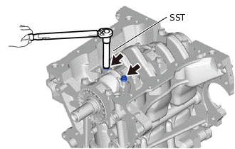
Using SST, install and alternately tighten the connecting rod bolts in several steps.
09205-16011
15 N*m
153 kgf*cm
11 ft.*lbf
Note:Do not turn the crankshaft.
-
Step 2:
-
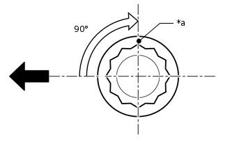
*a
Paint Mark

Engine Front
Mark the front of the connecting rod bolts with paint.
Further tighten the connecting rod bolts by 90° as shown in the illustration.
Note:Do not turn the crankshaft.
-
-
*a
Plastigage
*b
Mark
Measure the Plastigage at its widest point.
Standard Oil Clearance
0.025 to 0.065 mm (0.000984 to 0.00256 in.)
Maximum Oil Clearance
0.068 mm (0.00268 in.)
Note:Completely remove the Plastigage after the measurement.
Tip:If the oil clearance is not as specified, replace the connecting rod bearings. If necessary, inspect the crankshaft.
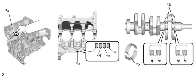
If replacing a connecting rod bearing, replace it with one that has the same number as its respective connecting rod bearing cap. Each connecting rod bearing standard thickness is indicated by a 1, 2, or 3 mark on its surface.
Standard Connecting Rod Large End Bore Diameter
Mark
Specified Condition
1
43.000 to 43.008 mm (1.69291 to 1.69323 in.)
2
43.009 to 43.016 mm (1.69326 to 1.69354 in.)
3
43.017 to 43.024 mm (1.69358 to 1.69385 in.)
Standard Connecting Rod Bearing Thickness
Mark
Specified Condition
1
1.492 to 1.495 mm (0.05874 to 0.05886 in.)
2
1.495 to 1.498 mm (0.05886 to 0.05898 in.)
3
1.498 to 1.501 mm (0.05898 to 0.05909 in.)
Standard Crankshaft Pin Diameter
Mark
Specified Condition
1, 2, 3
39.992 to 40.000 mm (1.57449 to 1.57480 in.)
Perform the inspection for each cylinder.
INSPECT CRANKSHAFT THRUST CLEARANCE
-
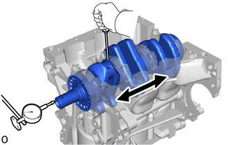
Using a dial indicator, measure the crankshaft thrust clearance while prying the crankshaft back and forth with a screwdriver.
Standard Thrust Clearance
0.02 to 0.22 mm (0.000787 to 0.00866 in.)
Maximum Thrust Clearance
0.30 mm (0.0118 in.)
Tip:If the crankshaft thrust clearance is more than the maximum, replace the crankshaft thrust washer uppers as a set. If necessary, replace the crankshaft.
The crankshaft thrust washer upper thickness is 1.94 to 1.99 mm (0.0764 to 0.0783 in.).
-
INSPECT NO. 1 OIL NOZZLE SUB-ASSEMBLY
-
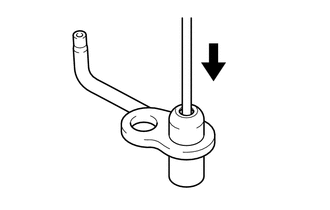
Push the check valve with a pin to check if it is stuck.
Tip:If stuck, replace the No. 1 oil nozzle sub-assembly.
Push the check valve with a pin to check if it moves smoothly.
Tip:If it does not move smoothly, clean or replace the No. 1 oil nozzle sub-assembly.
-
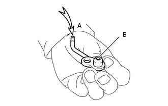
Apply air into (A). Check that air does not leak through (B).
Tip:If air leaks, clean or replace the No. 1 oil nozzle sub-assembly.
-
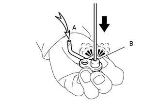
Push the check valve with a pin while applying air into (A). Check that air passes through (B). If air does not pass through (B), clean or replace the No. 1 oil nozzle sub-assembly.
-
INSPECT CYLINDER BLOCK SUB-ASSEMBLY FOR WARPAGE
-
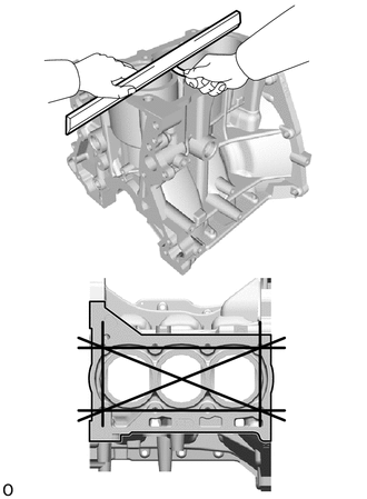
Using a precision straightedge and feeler gauge, check the surface which contacts the cylinder head gasket for warpage.
Maximum Warpage
0.05 mm (0.00197 in.)
Tip:If the warpage is greater than the maximum, replace the cylinder block sub-assembly.
-
INSPECT CYLINDER BORE
-
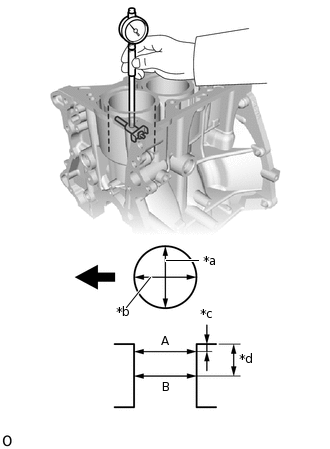
*a
Thrust Direction
*b
Axial Direction
*c
15 mm (0.591 in.)
*d
55 mm (2.17 in.)
Front
Using a cylinder gauge, measure the cylinder bore diameter at the positions (A) and (B) in both the thrust and axial directions.
Reference Diameter (New Parts)
71.000 to 71.013 mm (2.79527 to 2.79578 in.)
Maximum Diameter
71.133 mm (2.80051 in.)
Measurement Position
Measurement Position
Cylinder Bore Position
(A)
15 mm (0.591 in.)
(B)
55 mm (2.17 in.)
Tip:If the average diameter of the 4 positions is more than the maximum, replace the cylinder block sub-assembly.
-
INSPECT PISTON
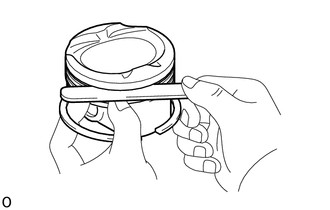
Using a gasket scraper, scrape off any carbon on the piston top.
-
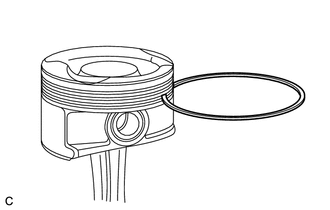
Using a groove cleaning tool or broken piston ring, clean the piston ring grooves.
CAUTION:Wear protective goggles.
Note:Do not damage the piston.
Using a brush and solvent, thoroughly clean the piston.
Note:Do not use a wire brush.
-
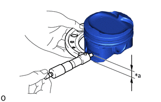
*a
11.9 mm (0.469 in.)
Using a micrometer, measure the piston diameter at a position 11.9 mm (0.469 in.) from the bottom of the piston (refer to the illustration).
Reference Piston Diameter (New Parts)
70.947 to 70.977 mm (2.7932 to 2.7944 in.)
Tip:If the diameter is not as specified, replace the piston and piston pin.
INSPECT PISTON OIL CLEARANCE
Subtract the piston diameter measurement from the cylinder bore diameter measurement.
Reference Oil Clearance (New Parts)
0.023 to 0.066 mm (0.000906 to 0.002598 in.)
Maximum Oil Clearance
0.108 mm (0.00425 in.)
Tip:The oil clearance between the piston and cylinder block sub-assembly can be calculated by subtracting the piston outer diameter in the thrust direction from the cylinder bore diameter.
Perform the measurement at the point with the most wear because there is joggling wear on the upper end of the piston ring sliding area.
If the piston oil clearance is more than the maximum, replace all the pistons and piston pins. If necessary, replace the cylinder block sub-assembly.
INSPECT PISTON RING GROOVE CLEARANCE
-
Using a feeler gauge, measure the clearance between a new piston ring and the wall of the ring groove.
Standard Ring Groove Clearance
Item
Specification
No. 1 Compression Ring
0.02 to 0.07 mm (0.000787 to 0.00276 in.)
No. 2 Compression Ring
0.02 to 0.06 mm (0.000787 to 0.00236 in.)
Oil Ring
0.07 to 0.15 mm (0.00276 to 0.00591 in.)
Tip:If the groove clearance is not as specified, replace the piston and piston pin.
-
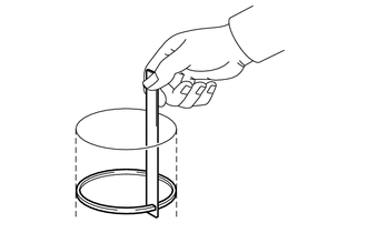
INSPECT PISTON RING END GAP
-
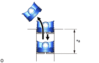
*a
55 mm (2.17 in.)
Using a piston, push the piston ring a little beyond the bottom of the ring travel, 55 mm (2.17 in.) from the top of the cylinder block sub-assembly.
-
Using a feeler gauge, measure the end gap.
Standard End Gap
Item
Specification
No. 1 Compression Ring
0.15 to 0.20 mm (0.00591 to 0.00787 in.)
No. 2 Compression Ring
0.40 to 0.50 mm (0.0157 to 0.0197 in.)
Oil Ring
0.10 to 0.40 mm (0.00394 to 0.0157 in.)
Maximum End Gap
Item
Specification
No. 1 Compression Ring
0.40 mm (0.0157 in.)
No. 2 Compression Ring
0.70 mm (0.0276 in.)
Oil Ring
0.69 mm (0.0272 in.)
Tip:If the end gap is more than the maximum, replace the piston ring set. If the end gap is more than the maximum even with a new piston ring set, replace the cylinder block sub-assembly.
-
INSPECT CONNECTING ROD SUB-ASSEMBLY
-
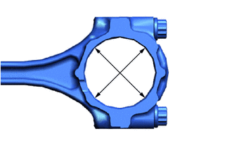
Using a cylinder gauge, measure the connecting rod sub-assembly big end diameter as shown in the illustration.
Standard Diameter
Mark
Specification
1
43.000 to 43.008 mm (1.69291 to 1.69322 in.)
2
43.009 to 43.016 mm (1.69326 to 1.69354 in.)
3
43.017 to 43.024 mm (1.69358 to 1.69385 in.)
Tip:If the diameter is not as specified, replace the connecting rod sub-assembly.
-
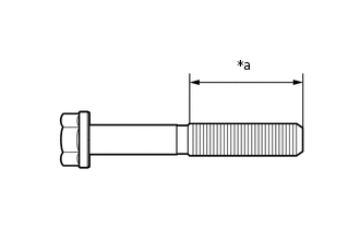
INSPECT CONNECTING ROD BOLT
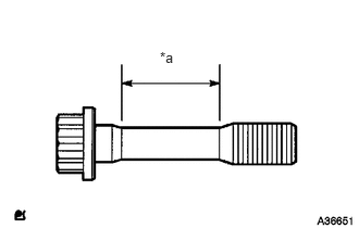
*a
Measurement Area
Using a vernier caliper, measure the diameter of the connecting rod bolt at several points within the area shown in the illustration.
Standard Diameter
6.6 to 6.7 mm (0.260 to 0.264 in.)
Minimum Diameter
6.4 mm (0.252 in.)
Tip:Diameter measurements should be done at several points.
If the diameter is less than the minimum, replace the connecting rod bolt with a new one. Failure to do so may lead to engine damage.
If there is any thread deformation, replace the connecting rod bolt with a new one.
INSPECT CRANKSHAFT
Inspect the runout.
-
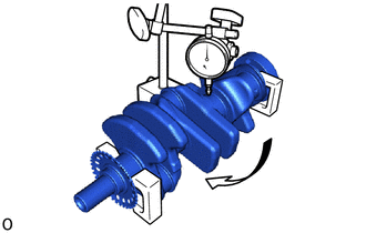
Using a dial indicator and V-blocks, measure the runout as shown in the illustration.
Maximum Runout
0.04 mm (0.00157 in.)
Tip:If the runout is greater than the maximum, replace the crankshaft.
-
Inspect the crankshaft journals.
-
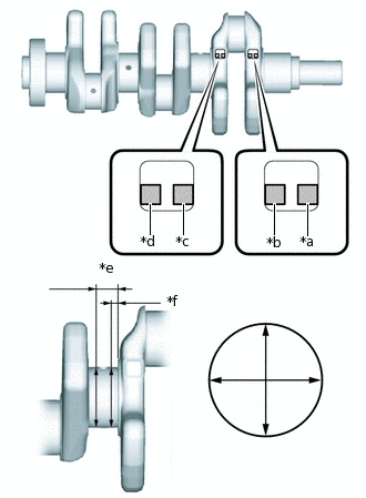
*a
No. 1
*b
No. 2
*c
No. 3
*d
No. 4
*e
10.4 mm (0.409 in.)
*f
5.5 mm (0.217 in.)
Using a micrometer, measure the diameter of each crankshaft journal.
Standard Diameter
43.988 to 44.000 mm (1.7318 to 1.7323 in.)
Tip:If the diameter is not as specified, check the crankshaft oil clearance.
Check each crankshaft journal for taper and out-of-round.
Maximum Taper and Out-of-round
0.003 mm (0.000118 in.)
Tip:If the taper or out-of-round is greater than the maximum, replace the crankshaft.
-
Inspect the crank pins.
-
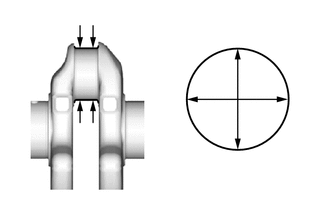
Using a micrometer, measure the diameter of each crank pin.
Standard Diameter
39.992 to 40.000 mm (1.5745 to 1.5748 in.)
Tip:If the diameter is not as specified, check the connecting rod oil clearance.
Inspect each crank pin for taper and out-of-round.
Maximum Taper and Out-of-round
0.003 mm (0.000118 in.)
Tip:If the taper or out-of-round is greater than the maximum, replace the crankshaft.
-
INSPECT CRANKSHAFT BEARING CAP SET BOLT
-
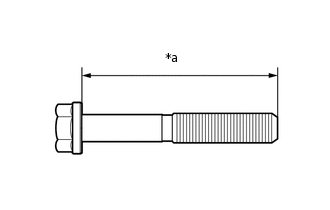
*a
Measurement Length
Using a vernier caliper, measure the length of the crankshaft bearing cap set bolt from the seat to the end.
Standard Length
67.0 to 68.0 mm (2.64 to 2.68 in.)
Maximum Length
68.5 mm (2.70 in.)
Tip:If the length is greater than the maximum, replace the crankshaft bearing cap set bolt with a new one. Failure to do so may lead to engine damage.
If there is any thread deformation, replace the crankshaft bearing cap set bolt with a new one.
-
*a
Measurement Area
Using a vernier caliper, measure the diameter of the bolt at several points within the area shown in the illustration.
Standard Diameter
9.94 to 9.96 mm (0.3913 to 0.3921 in.)
Minimum Diameter
9.60 mm (0.3780 in.)
Tip:Diameter measurements should be done at several points.
If the diameter is less than the minimum, replace the crankshaft bearing cap set bolt with a new one. Failure to do so may lead to engine damage.
If there is any thread deformation, replace the crankshaft bearing cap set bolt with a new one.
-
INSPECT CRANKSHAFT OIL CLEARANCE
Check the crankshaft journals and crankshaft bearings for pitting and scratches.
Install the crankshaft bearings.
Install the crankshaft thrust washer uppers.
Clean each crankshaft journal and crankshaft bearing.
Place the crankshaft on the cylinder block sub-assembly.
-
*a
Plastigage
Lay a strip of Plastigage across each journal.
Confirm the front marks and numbers and place the crankshaft bearing caps on the cylinder block sub-assembly.
Tip:A number mark is stamped on each crankshaft bearing cap to indicate the installation position.
Install the crankshaft bearing caps.
Note:Do not turn the crankshaft.
Remove the crankshaft bearing caps.
Measure the Plastigage at its widest point.
*a
Plastigage
*b
Number Mark
*c
No. 1
*d
No. 2
*e
No. 3
*f
No. 4
Standard Oil Clearance
0.018 to 0.047 mm (0.000709 to 0.00185 in.)
Maximum Oil Clearance
0.050 mm (0.00197 in.)
Note:Remove the Plastigage completely after the measurement.
Tip:If the oil clearance is greater than the maximum, replace the crankshaft bearings. If necessary, replace the crankshaft.
If replacing a crankshaft bearing, select a new one with the same number. If the number of the bearing cannot be determined, calculate the correct bearing number by adding together the numbers imprinted on the cylinder block sub-assembly and crankshaft. Then select a new bearing with the calculated number according to the following chart. There are 4 sizes of standard bearings, marked "2", "3", "4" or "5" accordingly.
EXAMPLE: Cylinder block mark "2" + Crankshaft mark "2" = Use bearing mark "4"
Standard Cylinder Block Journal Bore Diameter
Mark
Specified Condition
1
48.000 to 48.006 mm (1.88976 to 1.89000 in.)
2
48.006 to 48.012 mm (1.89000 to 1.89023 in.)
3
48.012 to 48.018 mm (1.89023 to 1.89047 in.)
Standard Crankshaft Journal Diameter
Mark
Specified Condition
1
43.995 to 44.000 mm (1.73208 to 1.73228 in.)
2
43.988 to 43.994 mm (1.73181 to 1.73204 in.)
Standard Bearing Center Wall Thickness
Mark
Specified Condition
2
1.995 to 1.997 mm (0.07854 to 0.07862 in.)
3
1.998 to 2.000 mm (0.07866 to 0.07874 in.)
4
2.001 to 2.003 mm (0.07878 to 0.07886 in.)
5
2.004 to 2.006 mm (0.07890 to 0.07898 in.)