ДАТЧИК ПОЛОЖЕНИЯ КОЛЕНЧАТОГО ВАЛА УСТАНОВКА
-
INSTALL CRANKSHAFT POSITION SENSOR
-
Apply a light coat of engine oil to the O-ring of the sensor.
-
Install the sensor with the bolt.
- Torque:
- 8.5 N*m { 87 kgf*cm, 75 in.*lbf }
-
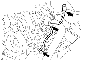
Install the connector to the connector bracket.
-
Attach the harness clamp.
-
Connect the sensor connector.
-
-
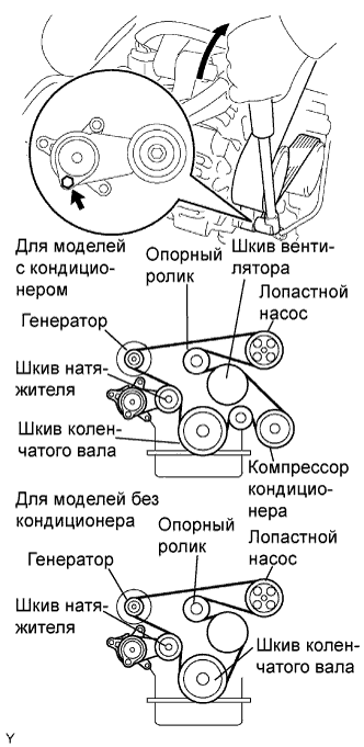
INSTALL NO. 1 COMPRESSOR MOUNTING BRACKET
Note
Install the No. 1 compressor mounting bracket exactly as described in the procedures below to properly secure and prevent damage to the fan and generator V belt.
-
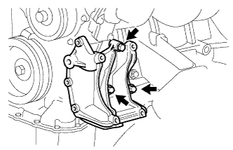
Temporarily install the No. 1 compressor mounting bracket with the 3 bolts.
Tech Tips
Temporarily install the No. 1 compressor mounting bracket with the 3 bolts so that the bracket can be moved by hand.
-
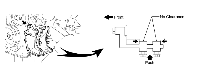
Push the No. 1 compressor mounting bracket toward the cylinder block as shown in the illustration and tighten the bolt B.
- Torque:
- 45 N*m { 459 kgf*cm, 33 ft.*lbf, for bolt B }
Tech Tips
Make sure there is no clearance between the cylinder block and No. 1 compressor mounting bracket as shown in the illustration.
-
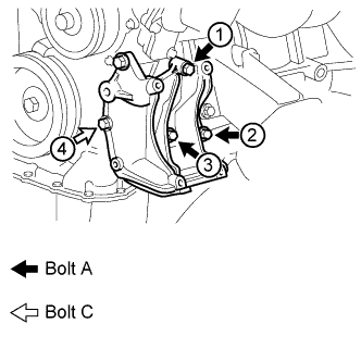
Uniformly tighten the 4 bolts in the order shown in the illustration.
- Torque:
- 45 N*m { 459 kgf*cm, 33 ft.*lbf, for bolt A }
- 24.5 N*m { 250 kgf*cm, 18 ft.*lbf, for bolt C }
-
-
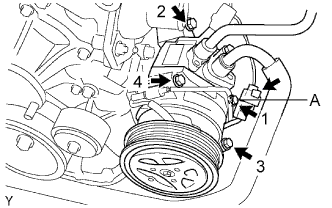
INSTALL COOLER COMPRESSOR ASSEMBLY
-
Temporarily install the compressor with the bolt labeled A.
-
Install the compressor completely by tightening the 4 bolts in the order shown in the illustration.
- Torque:
- 25 N*m { 255 kgf*cm, 18 ft.*lbf }
Note
In order to prevent misalignment, which causes belt rattle, tightening of the bolts must be performed in the order shown.
-
Connect the compressor connector.
-
Install the suction hose with the 2 bolts.
- Torque:
- 5.4 N*m { 55 kgf*cm, 48 in.*lbf }
-
-
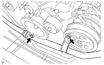
INSTALL DRIVE BELT
-
Install the drive belt to the pulleys except the drive belt tensioner pulley.
-
Use the hexagon-shaped part indicated by the arrow in the illustration to move the tensioner pulley downward and then install the drive belt to the tensioner pulley.
Note
-
The backside of the drive belt should face the tensioner pulley.
-
Check that the drive belt is properly set to each pulley.
-
-
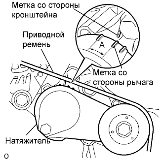
After a new belt has been installed, check that the tensioner indicator mark is within range A shown in the illustration.
-
-
CONNECT CABLE TO NEGATIVE BATTERY TERMINAL
-
PERFORM INITIALIZATION
-
Perform initialization Click here.
Note
Certain systems need to be initialized after disconnecting and reconnecting the cable from the negative (-) battery terminal.
-