CAMSHAFT INSTALLATION
CAUTION / NOTICE / HINT
When replacing the injectors (including shuffling the injectors between the cylinders), common rail, intake manifold or cylinder head sub-assembly, it is necessary to replace the injection pipes with new ones.
When replacing the fuel supply pump, common rail, intake manifold or cylinder head sub-assembly, it is necessary to replace the fuel inlet pipe with a new one.
PROCEDURE
INSPECT VALVE LASH ADJUSTER ASSEMBLY
INSTALL VALVE LASH ADJUSTER ASSEMBLY
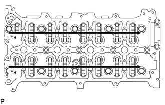
Install the 16 valve lash adjuster assemblies to the cylinder head sub-assembly.
Note:Install the valve lash adjuster assemblies to their original positions.
INSTALL NO. 1 VALVE ROCKER ARM SUB-ASSEMBLY
Install the 16 No. 1 valve rocker arm sub-assemblies to the 16 valve lash adjuster assemblies.
INSTALL CAMSHAFT
Install the No. 2 camshaft bearing cap.
-
*a
Apply Engine Oil
Apply clean engine oil to the cam of each camshaft, journals of the cylinder head sub-assembly and No. 1 valve rocker arm sub-assemblies.
-
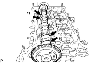
*1
No. 3 Cylinder Cam Lobe
*2
No. 1 Cylinder Cam Lobe
Place the No. 2 camshaft on the cylinder head sub-assembly as shown in the illustration so that the No. 1 cylinder cam lobe and No. 3 cylinder cam lobe face upward.
Note: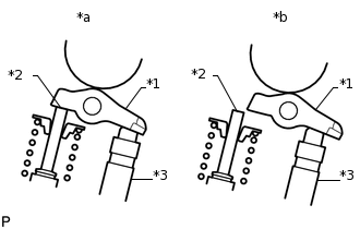
*1
No. 1 Valve Rocker Arm Sub-assembly
*2
Valve Stem
*3
Valve Lash Adjuster Assembly
*a
CORRECT
*b
INCORRECT
Before and after setting the camshaft and No. 2 camshaft on the cylinder head sub-assembly, check that the No. 1 valve rocker arm sub-assembly is firmly set to the valve lash adjuster assembly.
-
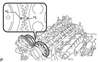
*1
Dot Mark
Align the camshaft and No. 2 camshaft timing mark (1 dot mark each).
Place the camshaft on the cylinder head sub-assembly.
-
Set the 8 No. 3 camshaft bearing caps and No. 1 camshaft bearing cap on the camshafts as shown in the illustration.
Tip:Make sure of the marks and numbers on the camshaft bearing caps and place them in the proper position and direction.
Partially tighten the 20 bolts.
-
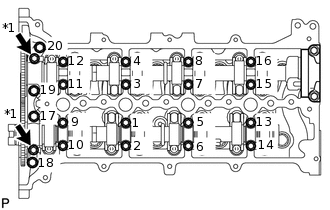
*1
Oil Pipe Seat
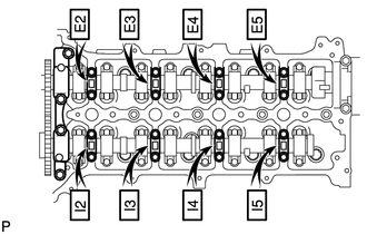
Uniformly tighten the bolts in several steps in the sequence shown in the illustration.
for 1 to 16
10 N*m
102 kgf*cm
7 ft.*lbf
for 17 to 20
21 N*m
214 kgf*cm
15 ft.*lbf
Install the 2 oil pipe seats.
17 N*m
173 kgf*cm
13 ft.*lbf
INSTALL CAMSHAFT TIMING SPROCKET
INSTALL OIL PUMP DRIVE GEAR
INSTALL NO. 1 CHAIN VIBRATION DAMPER
INSTALL CHAIN TENSIONER SLIPPER
INSTALL NO. 1 CHAIN TENSIONER ASSEMBLY
INSTALL FUEL SUPPLY PUMP ASSEMBLY
INSTALL TIMING CHAIN COVER SUB-ASSEMBLY
INSTALL CRANKSHAFT PULLEY
INSTALL ENGINE WATER PUMP ASSEMBLY
CONNECT CRANKSHAFT POSITION SENSOR WIRE HARNESS
INSTALL CAMSHAFT POSITION SENSOR
INSTALL OIL STRAINER SUB-ASSEMBLY
INSTALL OIL FILTER BRACKET
INSTALL OIL FILTER ELEMENT
INSTALL NO. 2 OIL PAN SUB-ASSEMBLY
INSTALL OIL PRESSURE SWITCHING VALVE ASSEMBLY
INSTALL CYLINDER HEAD COVER SUB-ASSEMBLY
INSTALL NOZZLE HOLDER CLAMP SEAT
INSTALL OIL FILLER CAP SUB-ASSEMBLY
INSTALL PCV HOSE
INSTALL NO. 1 WIRING HARNESS CLAMP BRACKET
INSTALL VACUUM TRANSMITTING HOSE ASSEMBLY
INSTALL NO. 1 VACUUM SWITCHING VALVE ASSEMBLY
INSTALL INJECTOR ASSEMBLY
INSTALL NO. 2 NOZZLE LEAKAGE PIPE
INSTALL NO. 3 FUEL HOSE
INSTALL FUEL TUBE SUB-ASSEMBLY
INSTALL FUEL HOSE PROTECTOR
INSTALL WATER INLET HOUSING
INSTALL NO. 4 WATER BY-PASS HOSE
INSTALL NO. 2 WATER BY-PASS PIPE
INSTALL NO. 1 OIL COOLER BRACKET
INSTALL NO. 1 TURBO OIL PIPE
INSTALL NO. 3 WATER BY-PASS PIPE
INSTALL NO. 8 WATER BY-PASS HOSE
INSTALL NO. 6 WATER BY-PASS HOSE
INSTALL OIL COOLER ASSEMBLY
INSTALL WATER BY-PASS HOSE
INSTALL NO. 1 CYLINDER BLOCK INSULATOR
INSTALL INTAKE MANIFOLD
INSTALL NO. 2 INTAKE MANIFOLD
INSTALL ENGINE COVER BRACKET
INSTALL GAS FILTER BRACKET
INSTALL NO. 1 GAS FILTER
INSTALL DIESEL TURBO PRESSURE SENSOR
INSTALL INTAKE MANIFOLD INSULATOR
INSTALL COMMON RAIL ASSEMBLY
INSTALL NO. 4 FUEL HOSE
INSTALL INJECTION PIPE SUB-ASSEMBLY
INSTALL FUEL INLET PIPE SUB-ASSEMBLY
INSTALL ENGINE OIL LEVEL DIPSTICK GUIDE
INSTALL ELECTRIC EGR CONTROL VALVE ASSEMBLY
INSTALL NO. 2 EGR PIPE SUB-ASSEMBLY
INSTALL EGR VALVE BRACKET
CONNECT NO. 8 WATER BY-PASS HOSE
INSTALL NO. 7 WATER BY-PASS HOSE
INSTALL DIESEL THROTTLE BODY ASSEMBLY
INSTALL V-RIBBED BELT TENSIONER ASSEMBLY
INSTALL ENGINE MOUNTING BRACKET
INSTALL NO. 4 WATER BY-PASS PIPE
INSTALL NO. 2 IDLER PULLEY SUB-ASSEMBLY
INSTALL NO. 1 IDLER PULLEY SUB-ASSEMBLY
INSTALL IDLER PULLEY COVER PLATE
INSTALL VACUUM PUMP ASSEMBLY
INSTALL GENERATOR ASSEMBLY
CONNECT ENGINE WIRE
INSTALL ENGINE ASSEMBLY
CONNECT CABLE TO NEGATIVE BATTERY TERMINAL
Note:When disconnecting the cable, some systems need to be initialized after the cable is reconnected.