STEERING LOCK SYSTEM Unable to Unlock Steering Wheel (Engine cannot Start)
| DTC Code | DTC Name |
|---|---|
| Unable to Unlock Steering Wheel (Engine cannot Start) |
DESCRIPTION
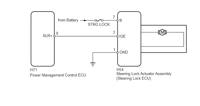
The power management control ECU supplies the power to activate the motor of the steering lock actuator assembly.
The steering lock actuator activates the steering lock motor and moves the lock bar into the steering column to lock the steering wheel.
The steering lock may not release when the lock bar gets stuck in the lock hole of the steering column. In this case, if an engine start operation is performed while shaking the steering wheel in the same manner as is done for a vehicle with a mechanical key, the lock bar will release.
The diagnosis information of the steering lock ECU is transmitted to the intelligent tester via the certification ECU as the steering lock ECU is not connected to the CAN communication system.
WIRING DIAGRAM
CAUTION / NOTICE / HINT
When the engine switch is off, the main body ECU may occasionally go into a non-active state called sleep mode. Therefore, before proceeding with the inspection, it is necessary to perform the following steps to wake up the ECU:
With the engine switch off, open the driver door. Then (with the engine switch still off) open and close any door several times at 1.5 second intervals.
If the steering lock actuator assembly (steering lock ECU) is replaced, with the engine switch off and the shift lever in P (except Manual Transaxle), open and close the driver side door to record the current lock position into the steering lock ECU. If this is not performed, the engine may not start.
When replacing the steering lock ECU, ID code box or certification ECU, registration must be performed. Refer to the Service Bulletin for the registration procedure.
PROCEDURE
CHECK ENGINE SWITCH (SWITCH CONDITION)
Check the power source mode change.
When the key is inside the vehicle and the shift lever is in P*, check that pressing the engine switch causes the power source mode to change as follows:
*: except Manual Transaxle
OK
off → on (ACC) → on (IG) → off
READ VALUE USING INTELLIGENT TESTER (LOCK/UNLOCK RECEIVE)
Use the Data List to check if the steering lock command is functioning properly.
Table 1. Entry&Start Tester Display
Measurement Item/Range
Normal Condition
Diagnostic Note
Unlock Request Receive
Steering lock unlock command reception status/NG or OK
NG: Unlock request not received
OK: Unlock request received
-
OK
The certification ECU receives an unlock request signal within 10 seconds of starting the engine, and OK is displayed on the intelligent tester screen.
READ VALUE USING INTELLIGENT TESTER (S CODE CHECK)Click here
CHECK HARNESS AND CONNECTOR (STEERING LOCK ECU - BATTERY AND BODY GROUND)
-
Disconnect the H54 steering lock ECU connector.
Measure the voltage and resistance according to the value(s) in the table below.
Standard Resistance
Tester Connection
Condition
Specified Condition
H54-1 (GND) - Body ground
Always
Below 1 Ω
Standard Voltage
Tester Connection
Condition
Specified Condition
H54-7 (B) - Body ground
Always
11 to 14 V
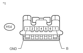
Table 2. Text in Illustration *1
Front view of wire harness connector
(to Steering Lock ECU)
REPAIR OR REPLACE HARNESS OR CONNECTOR
-
INSPECT STEERING LOCK ECU (IGE VOLTAGE)
-
Move the shift lever to P.*
*: except Manual Transaxle
Measure the voltage according to the value(s) in the table below.
Standard Voltage
Tester Connection
Condition
Specified Condition
H54-3 (IGE) - H54-1 (GND)
Steering lock motor operating immediately after turning engine switch from off to on (IG)
Below 1 V
H54-3 (IGE) - H54-1 (GND)
Steering lock motor not operating
11 to 14 V
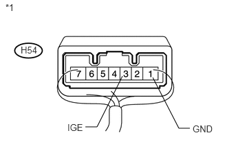
Table 3. Text in Illustration *1
Component with harness connected
(to Steering Lock ECU)
REPAIR OR REPLACE HARNESS OR CONNECTOR (STEERING LOCK ECU - POWER MANAGEMENT CONTROL ECU)
-
READ VALUE USING INTELLIGENT TESTER (S CODE CHECK)
Use the Data List to check if the S code certification is functioning properly.
Table 4. Entry&Start Tester Display
Measurement Item/Range
Normal Condition
Diagnostic Note
S Code Check
S code certification result/NG or OK
OK: S code certification result normal
NG: S code certification result abnormal
-
OK
OK is displayed on the intelligent tester.
REPLACE ID CODE BOXClick here
READ VALUE USING INTELLIGENT TESTER (L CODE CHECK)
Use the Data List to check if the L code certification is functioning properly.
Table 5. Entry&Start Tester Display
Measurement Item/Range
Normal Condition
Diagnostic Note
L Code Check
L code certification result/NG or OK
OK: L code certification result normal
NG: L code certification result abnormal
-
OK
OK is displayed on the intelligent tester.
REPLACE ID CODE BOXClick here
REPLACE STEERING LOCK ACTUATOR ASSEMBLY (STEERING LOCK ECU)
Replace the steering lock actuator assembly (steering lock ECU) (Click here).
CHECK STEERING LOCK RELEASE OPERATION
Turn the engine switch on (IG).
Operate the steering wheel and check the steering lock condition.
OK
Steering lock is released.
END (STEERING LOCK ECU IS DEFECTIVE)
REPLACE CERTIFICATION ECU
REPLACE ID CODE BOX
Replace the ID code box.
READ VALUE USING INTELLIGENT TESTER (S CODE CHECK)
Use the Data List to check if the S code certification is functioning properly.
Table 6. Entry&Start Tester Display
Measurement Item/Range
Normal Condition
Diagnostic Note
S Code Check
S code certification result/NG or OK
OK: S code certification result normal
NG: S code certification result abnormal
-
OK
OK is displayed on the intelligent tester.
END (ID CODE BOX IS DEFECTIVE)
REPLACE CERTIFICATION ECU
REPLACE ID CODE BOX
Replace the ID code box.
READ VALUE USING INTELLIGENT TESTER (L CODE CHECK)
Use the Data List to check if the L code certification is functioning properly.
Table 7. Entry&Start Tester Display
Measurement Item/Range
Normal Condition
Diagnostic Note
L Code Check
L code certification result/NG or OK
OK: L code certification result normal
NG: L code certification result abnormal
-
OK
OK is displayed on the intelligent tester.
END (ID CODE BOX IS DEFECTIVE)