CRUISE CONTROL SYSTEM(for 1WW) Cruise Control Switch Circuit
| DTC Code | DTC Name |
|---|---|
| Cruise Control Switch Circuit |
DESCRIPTION
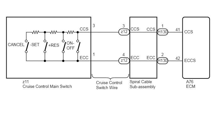
The cruise control main switch outputs the signals of the power source for cruise control and the signals of the various operation switches to the ECM.
The ECM performs cruise control in accordance with the signals from the cruise control main switch.
WIRING DIAGRAM
PROCEDURE
READ VALUE USING GTS (CRUISE CONTROL SWITCH)
Use the Data List to check if the cruise control main switch is functioning properly (Click here).
Table 1. Cruise Control Tester Display
Measurement Item/Range
Normal Condition
Diagnostic Note
Cruise Control Switch
Cruise control switch signal / ON or OFF
ON: Cruise control switch (ON-OFF switch) pushed
OFF: Cruise control switch (ON-OFF switch) released
-
CANCEL SW
CANCEL switch signal / ON or OFF
ON: CANCEL switch on
OFF: CANCEL switch off
-
-SET SW
-SET switch signal / ON or OFF
ON: -SET switch on
OFF: -SET switch off
-
+RES SW
+RES switch signal / ON or OFF
ON: +RES switch on
OFF: +RES switch off
-
OK
On screen, each item changes between ON and OFF according to above chart.
INSPECT SPIRAL CABLE SUB-ASSEMBLY
Remove the spiral cable sub-assembly (Click here).
Inspect the spiral cable sub-assembly (Click here).
INSPECT CRUISE CONTROL SWITCH WIRE
Disconnect the z12 spiral cable connector.
Disconnect the z11 switch connector.
Measure the resistance according to the value(s) in the table below.
Standard Resistance
Tester Connection
Condition
Specified Condition
z12-3 (CCS) - z11-3 (CCS)
Always
Below 1 Ω
z12-4 (ECC) - z11-1 (ECC)
z12-3 (CCS) - Body ground
Always
10 kΩ or higher
z12-4 (ECC) - Body ground
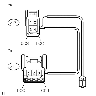
Table 2. Text in Illustration *a
Front view of wire harness connector
(to Spiral Cable)
*b
Front view of wire harness connector
(to Cruise Control Main Switch)
REPLACE CRUISE CONTROL SWITCH WIRE
INSPECT CRUISE CONTROL MAIN SWITCH
Remove the cruise control main switch (Click here).
Inspect the cruise control main switch (Click here).
CHECK HARNESS AND CONNECTOR (SPIRAL CABLE SUB-ASSEMBLY - ECM AND BODY GROUND)
Disconnect the H130 spiral cable connector.
Disconnect the A76 ECM connector.
Measure the resistance according to the value(s) in the table below.
Standard Resistance
Tester Connection
Condition
Specified Condition
H130-1 (CCS) - A76-41 (CCS)
Always
Below 1 Ω
H130-2 (ECC) - A76-42 (ECCS)
H130-2 (ECC) - Body ground
10 kΩ or higher
H130-1 (CCS) - Body ground
REPAIR OR REPLACE HARNESS OR CONNECTOR