FUEL INJECTOR REMOVAL
CAUTION / NOTICE / HINT
After the engine has stopped, wait at least 1 minute before releasing the high pressure lines.
When working on the fuel circuit, protect the generator assembly against dirt contamination.
Cover the generator assembly with suitable materials.
Failure to comply with this procedure may result in a generator assembly malfunction.
-
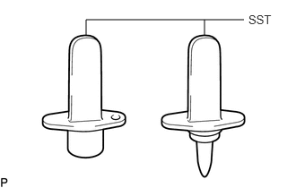
After disconnecting the pressure line, it is absolutely essential to seal the injector assemblies and the common rail assembly with SST.
SST
PZ4TB-04941-79
PROCEDURE
PRECAUTION
Note:After turning the ignition switch off, waiting time may be required before disconnecting the cable from the battery terminal. Therefore, make sure to read the disconnecting the cable from the battery terminal notice before proceeding with work (Click here).
DISCONNECT CABLE FROM NEGATIVE BATTERY TERMINAL
Note:When disconnecting the cable, some systems need to be initialized after the cable is reconnected (Click here).
REMOVE NO. 1 ENGINE COVER
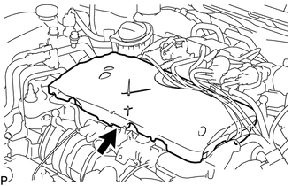
REMOVE ENGINE COVER
REMOVE INJECTION PIPE SUB-ASSEMBLY
 Note:
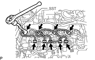
Note:Reset SST in a timely manner to prevent bending of pressure lines.
Using SST, loosen the 4 union nuts at the common rail assembly end of the 2 No. 1 injection pipe sub-assemblies and 2 No. 2 injection pipe sub-assemblies.
SST
PZ4TB-04959-10
Using SST, loosen the 4 union nuts at the 4 injector assembly ends of the 2 No. 1 injection pipe sub-assemblies and 2 No. 2 injection pipe sub-assemblies.
SST
PZ4TB-04959-10
Remove the 2 No. 1 injection pipe sub-assemblies and 2 No. 2 injection pipe sub-assemblies.
REMOVE CAMSHAFT POSITION SENSOR
DISCONNECT NOZZLE LEAKAGE PIPE ASSEMBLY
-
Disconnect the connector and detach the 2 clamps to disconnect the wire harness (Click here).
-
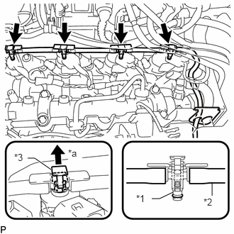
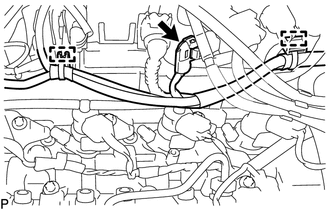
Pull up the 4 clips and disconnect the nozzle leakage pipe assembly from the 4 injector assemblies as shown in the illustration.
Table 1. Text in Illustration *1
Sealing Ring
*2
Leakage Line
*3
Clip
*a
Pull Up
Note:If a sealing ring is damaged, the entire leakage line of a cylinder group must be replaced.
Remove the 4 sealing rings from the nozzle leakage pipe assembly.
-
REMOVE INJECTOR ASSEMBLY
-
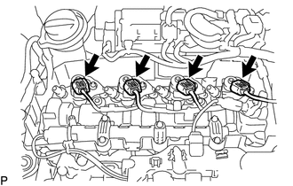
Disconnect the 4 injector assembly connectors.
-
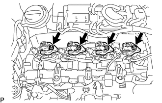
Using an E10 "TORX" socket wrench, remove the 4 bolts and 4 centering rings.
Remove the 4 clamping claws from the 4 injector assemblies.
-
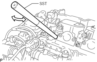
Remove the 4 injector assemblies from the cylinder head cover sub-assembly.
Pull out the injector assembly with light rotational movements.
SST
PZ4TB-04942-79
Tip:If an injector assembly is stuck tight, mount SST (rod) to the pressure line connection.
Move injector assembly with SST (rod) only by a few degrees.
-