LIGHTING SYSTEM High Beam Headlight Circuit
DESCRIPTION
The illumination of the high beam headlights is controlled by the headlight leveling ECU assembly.
WIRING DIAGRAM
-
for Triple Beam Headlight without Adaptive High Beam System:
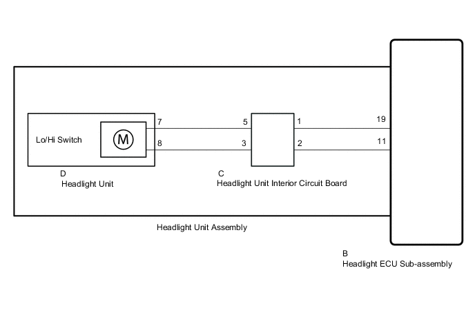
-
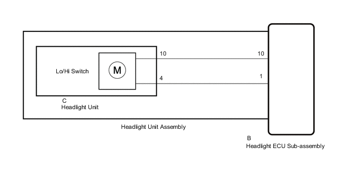
for Single Beam Headlight:
CAUTION / NOTICE / HINT
Note
After the headlight ECU sub-assembly LH is replaced, vehicle information registration and initialization are necessary.
PROCEDURE
-
CONFIRM MODEL
-
Choose the model to be inspected.
Result Result Proceed to for Triple Beam Headlight without Adaptive High Beam System A for Single Beam Headlight B
B 
PERFORM ACTIVE TEST USING GTS (HEADLIGHT HI RELAY) Click here
A 
-
-
PERFORM ACTIVE TEST USING GTS (HEADLIGHT HI RELAY)
-
Using the GTS, perform the Active Test.
Body Electrical > AFS > Active TestTester Display Measurement Item Control Range Diagnostic Note Headlight High Beam Illuminates the high beam headlights OFF or ON -
Body Electrical > AFS > Active TestTester Display Headlight High Beam Result Result Proceed to The Active Test is performed normally A The Active Test is not performed normally for the left side light only B The Active Test is not performed normally for the right side light only C
A 
PROCEED TO NEXT SUSPECTED AREA SHOWN IN PROBLEM SYMPTOMS TABLE Click here
C
CHECK HEADLIGHT UNIT ASSEMBLY RH Click here
B
-
-
CHECK HEADLIGHT UNIT ASSEMBLY LH
-
Interchange the headlight unit assembly LH with RH and connect the connectors to them.
-
Check that the high beam light LH operate normally.
OK High beam light LH operate normally. Result Proceed to OK NG
NG
REPLACE HEADLIGHT ECU SUB-ASSEMBLY LH Click here
OK
-
-
INSPECT HEADLIGHT ECU SUB-ASSEMBLY LH
-
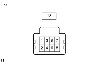
*a Component without harness connected
(Headlight Unit LH)
Remove the headlight unit LH.
-
Connect the No. 1 headlight ECU sub-assembly LH connectors.
-
Measure the voltage according to the value (s) in the table below.
Standard Voltage Tester Connection Condition Specified Condition D-7 - D-8 High beam headlights illuminated 11 to 14 V Result Proceed to OK NG
OK
REPLACE HEADLIGHT UNIT LH Click here
NG
REPLACE HEADLIGHT UNIT ASSEMBLY LH Click here
-
-
CHECK HEADLIGHT UNIT ASSEMBLY RH
-
Interchange the headlight unit assembly RH with LH and connect the connectors to them.
-
Check that the high beam light RH operate normally.
OK High beam light RH operate normally. Result Proceed to OK NG
NG
REPLACE HEADLIGHT ECU SUB-ASSEMBLY RH Click here
OK
-
-
INSPECT HEADLIGHT ECU SUB-ASSEMBLY RH
-
*a Component without harness connected
(Headlight Unit RH)
Remove the headlight unit RH.
-
Connect the No. 1 headlight ECU sub-assembly RH connectors.
-
Measure the voltage according to the value (s) in the table below.
Standard Voltage Tester Connection Condition Specified Condition D-7 - D-8 High beam headlights illuminated 11 to 14 V Result Proceed to OK NG
OK
REPLACE HEADLIGHT UNIT RH Click here
NG
REPLACE HEADLIGHT UNIT ASSEMBLY RH Click here
-
-
PERFORM ACTIVE TEST USING GTS (HEADLIGHT HI RELAY)
-
Using the GTS, perform the Active Test.
Body Electrical > HL AutoLeveling > Active TestTester Display Measurement Item Control Range Diagnostic Note Headlight High Beam Illuminates the high beam headlights OFF or ON -
Body Electrical > HL AutoLeveling > Active TestTester Display Headlight High Beam Result Result Proceed to The Active Test is performed normally A The Active Test is not performed normally for the left side light only B The Active Test is not performed normally for the right side light only C
A
PROCEED TO NEXT SUSPECTED AREA SHOWN IN PROBLEM SYMPTOMS TABLE Click here
C
CHECK HEADLIGHT UNIT ASSEMBLY RH Click here
B
-
-
CHECK HEADLIGHT UNIT ASSEMBLY LH
-
Interchange the headlight unit assembly LH with RH and connect the connectors to them.
-
Check that the high beam light LH operate normally.
OK High beam light LH operate normally. Result Proceed to OK NG
NG
REPLACE HEADLIGHT ECU SUB-ASSEMBLY LH Click here
OK
-
-
INSPECT HEADLIGHT UNIT ASSEMBLY LH
-
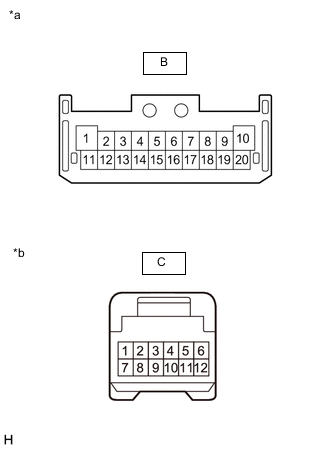
*a Component without harness connected
(Headlight ECU Sub-assembly LH)
*b Component without harness connected
(Headlight Unit LH)
Remove the headlight unit LH.
-
Measure the resistance according to the value(s) in the table below.
Standard Resistance Tester Connection Condition Specified Condition B-10 - C-10 Always Below 1 Ω B-1 - C-4 Always Below 1 Ω Result Proceed to OK NG
OK
REPLACE HEADLIGHT UNIT LH Click here
NG
REPLACE HEADLIGHT UNIT ASSEMBLY LH Click here
-
-
CHECK HEADLIGHT UNIT ASSEMBLY RH
-
Interchange the headlight unit assembly RH with LH and connect the connectors to them.
-
Check that the high beam light RH operate normally.
OK High beam light RH operate normally. Result Proceed to OK NG
NG
REPLACE HEADLIGHT ECU SUB-ASSEMBLY RH Click here
OK
-
-
INSPECT HEADLIGHT UNIT ASSEMBLY RH
-
*a Component without harness connected
(Headlight ECU Sub-assembly RH)
*b Component without harness connected
(Headlight Unit RH)
Remove the headlight unit RH.
-
Measure the resistance according to the value(s) in the table below.
Standard Resistance Tester Connection Condition Specified Condition B-10 - C-10 Always Below 1 Ω B-1 - C-4 Always Below 1 Ω Result Proceed to OK NG
OK
REPLACE HEADLIGHT UNIT RH Click here
NG
REPLACE HEADLIGHT UNIT ASSEMBLY RH Click here
-