REAR LOWER ARM REMOVAL
CAUTION / NOTICE / HINT
Use the same procedure for the RH and LH sides.
The procedure listed below is for the LH side.
PROCEDURE
REMOVE REAR WHEEL
REMOVE REAR HEIGHT CONTROL SENSOR SUB-ASSEMBLY LH (w/ Automatic Headlight Beam Level Control System)
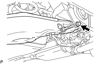
REMOVE REAR SHOCK ABSORBER ASSEMBLY LH
REMOVE REAR NO. 1 SUSPENSION ARM ASSEMBLY LH
-
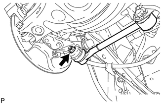
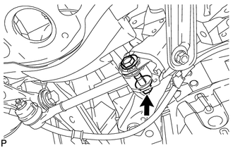
Remove the nut from the axle carrier.
-
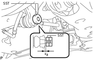
*a
1 mm (0.0394 in.)
Install SST to the rear No. 1 suspension arm as shown in the illustration.
09960-20010
09961-02060
Note:Make sure that the clearance measurement between SST and the rear axle assembly is 1 mm (0.0394 in.).
Tip:Use 2 SST of the same type.
Using SST, disconnect the rear No. 1 suspension arm from the rear axle carrier as shown in the illustration.
09960-20010
09961-02010
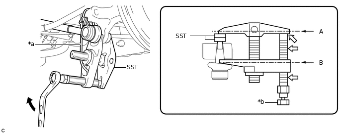
*a
Tie the string so there is no slack
*b
Place the wrench here

Turn

Molybdenum grease
CAUTION:Apply molybdenum grease to the threads and end of SST bolt.
Note:Install SST so that A and B are parallel.
Be sure to turn the part indicated in the illustration with a wrench.
Do not damage the front lower ball joint dust cover.
Be sure to tie the string of SST to the vehicle to prevent SST from dropping.
-
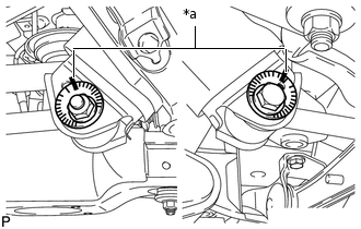
*a
Matchmark
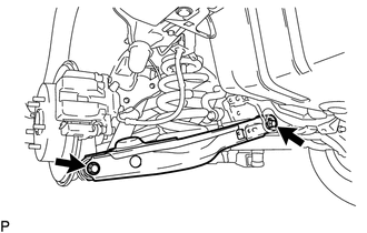
Put matchmarks on the rear suspension toe adjust cam, No. 2 camber adjust cam and rear suspension member.
-
Remove the nut, No. 2 camber adjust cam, rear suspension toe adjust cam and rear No. 1 suspension arm assembly LH.
-
REMOVE REAR STABILIZER LINK ASSEMBLY LH
LOOSEN REAR NO. 2 SUSPENSION ARM ASSEMBLY LH
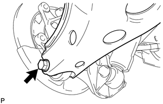
Loosen the 2 bolts of the rear No. 2 suspension arm.
Note:Do not remove the bolts and nuts, only loosen them.
Since a stopper nut is used, loosen the bolt.
REMOVE REAR COIL SPRING LH
-
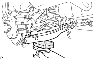
Support the No. 2 suspension arm LH with a jack.
Note:Place a wooden or rubber block between the jack and arm.
-
Remove the bolt located on the rear axle carrier of the rear No. 2 suspension arm.
Note:Hold the nut and remove the bolt.
Lower the jack gradually to remove the rear coil spring together with the rear upper coil spring insulator.
-
REMOVE REAR UPPER COIL SPRING INSULATOR LH
Remove the rear upper coil spring insulator from the rear coil spring.
REMOVE REAR LOWER COIL SPRING INSULATOR LH
Remove the rear lower coil spring insulator from the rear No. 2 suspension arm.
REMOVE REAR NO. 2 SUSPENSION ARM ASSEMBLY LH
Remove the bolt, nut and rear No. 2 suspension arm from the suspension member.
Note:Since a stopper nut is used, loosen the bolt.