MONITOR SYSTEM DETAILS
-
FUNCTION OF MAIN COMPONENTS
Component Function Radio and Display Receiver Assembly Displays the image transmitted by the rear television camera assembly on the screen. Rear Television Camera Assembly Captures images in rear of the vehicle and outputs visual signals to the radio and display receiver assembly. ECM Transmits the vehicle signal to the radio and display receiver assembly. Back-up Light Switch Assembly*1 Transmits the on/off signal of the back-up light switch assembly to the ECM. Park/Neutral Position Switch Assembly*2 Transmits the shift position signal to the ECM.
-
*1: Models with manual transmission
-
*2: Models with automatic transmission
-
-
OPERATING CONDITION
-
The rear view monitor system operates when the following conditions are met:
-
The ignition switch is ON.
-
The back-up light switch is ON.*1
-
The shift lever is moved to R.*2
-
*1: Models with manual transmission
-
*2: Models with automatic transmission
-
-
-
FUNCTION
-
Area Displayed on Screen
-
Rear Television Camera Assembly
-
On the display, objects on the right of the vehicle appear on the right side of the display panel, and objects on the left of the vehicle appear on the left side of the display panel.
-
The television camera uses a wide-angle lens. The perceived distance from images that appear on the screen differs from the actual distance.
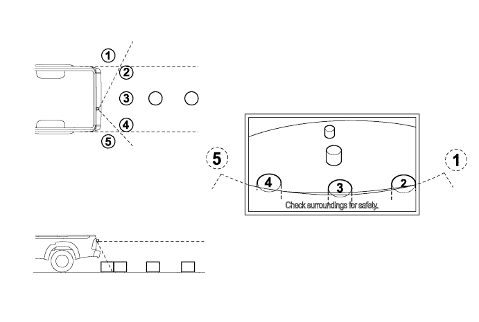
Tech Tips
The area displayed on the screen may vary in accordance with vehicle status or road conditions. The area covered by the television camera is limited. The television camera does not show objects close to either corner of the bumper or under the bumper.
-
-
-
-
CONSTRUCTION
-
Rear Television Camera Assembly
-
The rear television camera assembly consists of a wide-angle lens and a Charge Coupled Device (CCD).
-
An image captured by the rear view television camera lens is converted into electrical signals in accordance with the light intensity by using the CCD image element, and the signals are then output to the radio and display receiver assembly.
-
The image output from the rear television camera assembly is reversed to match the rear view seen from the inside rear view mirror. Therefore, the view actually seen is displayed on the screen in the horizontal reverse.
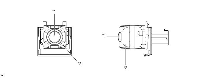
Text in Illustration *1 Wide-angle Lens *2 Rear Television Camera Assembly
-
-
-
DIAGNOSIS
-
The monitor system is equipped with a diagnosis function which can display the diagnosis menus. For details, refer to the corresponding Repair Manual for this model.
-