CANVAS TOP SYSTEM TERMINALS OF ECU
CHECK SLIDING ROOF CONTROL ECU ASSEMBLY
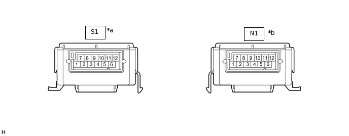
*a
Connector Color: Brown
*b
Connector Color: Black
Disconnect the N1 sliding roof control ECU assembly connector.
Measure the resistance and voltage according to the value(s) in the table below.
Tip:Measure the values on the wire harness side with the connector disconnected.
Terminal No. (Symbol)
Wiring Color
Terminal Description
Condition
Specified Condition
N1-2 (B) - N1-1 (E)
R - B
Battery power supply
Always
11 to 14 V
N1-3 (IG) - N1-1 (E)
O - B
IG power supply
Ignition switch off
Below 1 V
N1-3 (IG) - N1-1 (E)
O - B
IG power supply
Ignition switch ON
11 to 14 V
N1-1 (E) - Body ground
B - Body ground
Ground
Always
Below 1 Ω
Reconnect the N1 sliding roof control ECU assembly connector.
Measure the voltage according to the value(s) in the table below.
Terminal No. (Symbol)
Wiring Color
Terminal Description
Condition
Specified Condition
N1-5 (OPN) - N1-1 (E)
V - B
Open switch input signal
Ignition switch ON, open switch on
Below 1 V
N1-5 (OPN) - N1-1 (E)
V - B
Open switch input signal
Ignition switch ON, open switch off
11 to 14 V
N1-4 (CLS) - N1-1 (E)
GR - B
Close switch input signal
Ignition switch ON, close switch on
Below 1 V
N1-4 (CLS) - N1-1 (E)
GR - B
Close switch input signal
Ignition switch ON, close switch off
11 to 14 V
S1-2 (VCC) - S1-1 (SGND)
W - BR
Power supply of Hall-ICs sensor
Ignition switch ON
11 to 14 V
S1-3 (PLS1) - S1-1 (SGND)
G - BR
Hall-IC sensor input signal
Ignition switch ON, open or close switch on
Pulse generation
S1-4 (PLS2) - S1-1 (SGND)
L - BR
Hall-IC sensor input signal
Ignition switch ON, open or close switch on
Pulse generation
S1-5 (CLOSE) - N1-1 (E)
V - B
Close switch output signal
Ignition switch ON, close switch on
11 to 14 V
S1-6 (OPEN) - N1-1 (E)
GR - B
Open switch output signal
Ignition switch ON, open switch on
11 to 14 V