CYLINDER HEAD REASSEMBLY
PROCEDURE
INSTALL CYLINDER HEAD OIL ORIFICE
-
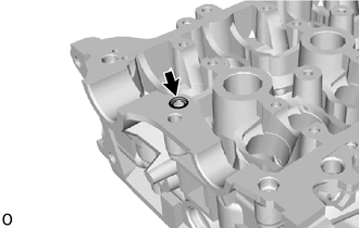
Tap in the cylinder head oil orifice to the cylinder head sub-assembly.
-
INSTALL VALVE SPRING SEAT
-
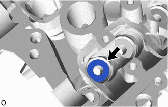
Install the 12 valve spring seats to the cylinder head sub-assembly.
-
INSTALL VALVE STEM OIL SEAL
-
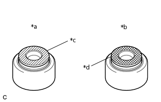
*a
Intake Side
*b
Exhaust Side
*c
Gray
*d
Black
Apply a light coat of engine oil to 12 new valve stem oil seals.
Note:Pay close attention when installing the intake valve stem oil seal or exhaust valve stem oil seal. For example, installing the intake valve stem oil seal to the exhaust side or installing the exhaust valve stem oil seal to the intake side can cause installation problems later.
Tip:The intake valve stem oil seal is gray and the exhaust valve stem oil seal is black.
-
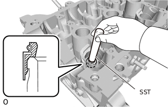
Using SST, push in the 12 valve stem oil seals.
09201-41020
Note:Failure to use SST will cause the valve stem oil seal to be damaged or improperly seated.
-
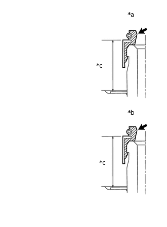
*a
Intake Side
*b
Exhaust Side
*c
Depth
Make sure that each valve stem oil seal is pushed in to the specified depth as shown in the illustration.
Standard Depth
Intake Side
10.0 to 11.6 mm (0.394 to 0.457 in.)
Exhaust Side
9.4 to 11.0 mm (0.370 to 0.433 in.)
-
INSTALL INTAKE VALVE
Place the cylinder head sub-assembly on wooden blocks.
-
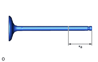
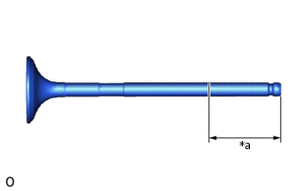
*a
Application Width
Apply engine oil to the tip area of the intake valve as shown in the illustration.
Standard Application Width
30 mm (1.18 in.) or more
Install the intake valve, inner compression spring and valve spring retainer to the cylinder head sub-assembly.
Note:Install the same parts in the same combination to their original locations.
-
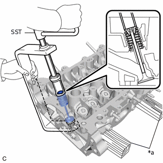
*a
Wooden Block
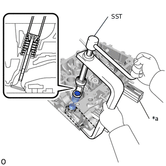
Using SST, compress the inner compression spring and install the valve spring retainer lock.
09202-70020
09202-00010
-
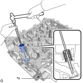
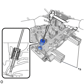
*a
Wooden Block
Using a pin punch, gently tap the valve stem tip to ensure that it is fitted properly.
Note:Be careful not to damage the intake valve stem tip.
Be careful not to damage the valve spring retainer.
INSTALL EXHAUST VALVE
-
*a
Application Width
Apply engine oil to the tip area of the exhaust valve as shown in the illustration.
Standard Application Width
30 mm (1.18 in.) or more
Install the exhaust valve, inner compression spring and valve spring retainer to the cylinder head sub-assembly.
Note:Install the same parts in the same combination to their original locations.
-
*a
Wooden Block
Using SST, compress the inner compression spring and install the valve spring retainer lock.
09202-70020
09202-00010
-
*a
Wooden Block
Using a pin punch, gently tap the valve stem tip to ensure that it is fitted properly.
Note:Be careful not to damage the exhaust valve stem tip.
Be careful not to damage the valve spring retainer.
-
APPLY ENGINE OIL
-
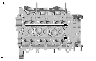
*a
Apply engine oil
Apply engine oil to the top surfaces of the valves as shown in the illustration.
-