РАСПРЕДВАЛ СНЯТИЕ

CAUTION / NOTICE / HINT
The necessary procedures (adjustment, calibration, initialization, or registration) that must be performed after parts are removed, installed, or replaced during the camshaft removal/installation are shown below.
| Replacement Part or Procedure | Necessary Procedures | Effects/Inoperative when not Performed | Link |
|---|---|---|---|
| Battery terminal is disconnected/reconnected | Drive the vehicle until stop and start control is permitted (approximately 15 to 40 minutes) | Stop and start system | |
| Memorize steering angle neutral point | Panoramic view monitor system | ||
| Initialize back door lock | Power door lock control system | ||
| Initialize servo motor | Air conditioning system | ||
| Reset slide door close position | Power slide door system | ||
| Reset back door close position | Power back door system | ||
|
Inspection After Repair |
|
CAUTION:
-
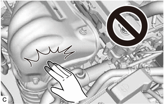
To prevent burns, do not touch the engine, exhaust manifold or other high temperature components while the engine is hot.
PROCEDURE
-
DISCONNECT CABLE FROM NEGATIVE BATTERY TERMINAL
Note
When disconnecting the cable, some systems need to be initialized after the cable is reconnected.
-
REMOVE FRONT WHEEL RH
-
REMOVE REAR ENGINE UNDER COVER RH
-
REMOVE OUTER COWL TOP PANEL SUB-ASSEMBLY
-
REMOVE RADIATOR RESERVE TANK ASSEMBLY
-
REMOVE RADIATOR RESERVE TANK BRACKET
-
REMOVE AIR CLEANER CAP SUB-ASSEMBLY
-
REMOVE AIR CLEANER CASE SUB-ASSEMBLY
-
REMOVE AIR CONDITIONER TUBE ASSEMBLY
-
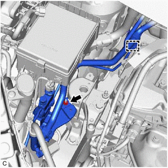
Remove the clamp and nut and disconnect the air conditioner tube assembly.
-
-
DISCONNECT ENGINE WIRE
-
Disconnect the 17 connectors and 10 clamps.
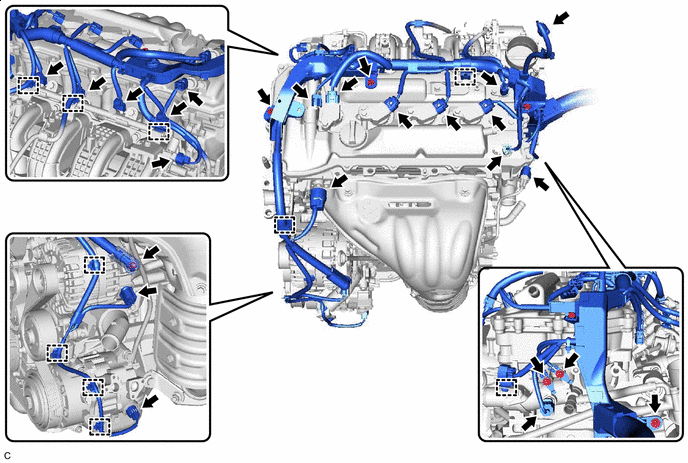

Connector 
Bolt 
Nut - - -
Remove the 3 bolts and 4 nuts and disconnect the engine wire from the engine assembly.
-
-
REMOVE IGNITION COIL ASSEMBLY
-
REMOVE CYLINDER HEAD COVER SUB-ASSEMBLY
-
SET NO. 1 CYLINDER TO TDC/COMPRESSION
-
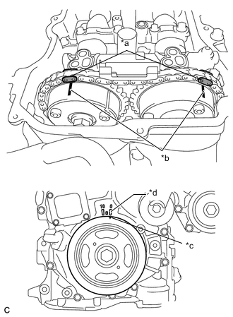
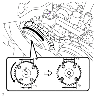
*a Paint Mark *b Timing Mark *c Timing Notch (Groove) *d Timing Mark "0°" Turn the crankshaft pulley until its timing notch (groove) and the timing mark "0" of the timing chain cover sub-assembly are aligned.
-
Check that both timing marks on the camshaft timing gear assembly and camshaft timing exhaust gear assembly are facing upward as shown in the illustration. If not, turn the crankshaft 1 revolution (360°) to align the timing marks as shown in the illustration.
-
Place paint marks on the chain sub-assembly in alignment with the timing marks on the camshaft timing gear assembly and camshaft timing exhaust gear assembly.
-
-
REMOVE TIMING CHAIN COVER PLATE
-
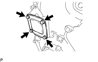
Remove the 4 bolts, timing chain cover plate and gasket.
-
-
REMOVE NO. 1 CHAIN TENSIONER ASSEMBLY
-
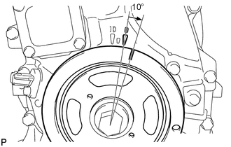
Turn the crankshaft pulley approximately 10° clockwise.
-
Turn the crankshaft pulley approximately 10° counterclockwise.
-
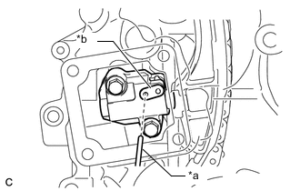
*a Pin *b Stopper Plate Align the holes of the stopper plate and No. 1 chain tensioner assembly, and insert a pin into the stopper plate hole to lock the No. 1 chain tensioner assembly.
-

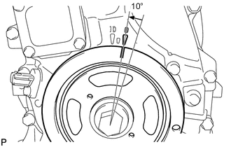
Turn the crankshaft pulley approximately 10° clockwise.
-
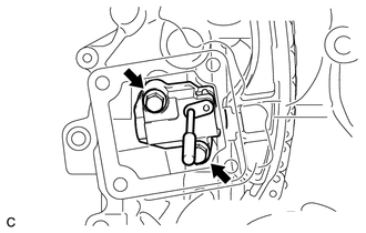
Remove the 2 bolts, No. 1 chain tensioner assembly and gasket.
Note
Be careful not to drop the gasket inside the timing chain cover sub-assembly.
-

Turn the crankshaft pulley approximately 10° counterclockwise.
-
-
REMOVE TIMING CHAIN GUIDE
-
REMOVE OIL PUMP RELIEF VALVE PLUG
-
*a 14 mm Union Nut Wrench *b 14 mm Straight Hexagon Wrench Turn Using a 14 mm straight hexagon wrench and 14 mm union nut wrench, remove the oil pump relief valve plug and gasket.
-
-
REMOVE CAMSHAFT TIMING GEAR ASSEMBLY
-
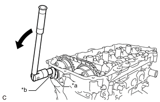
*a Hold Turn Using a wrench to hold the hexagonal portion of the camshaft, remove the bolt from the camshaft.
Note
Be careful not to damage the cylinder head sub-assembly or spark plug tube with the wrench.
-
Separate the camshaft timing gear assembly from the camshaft.
-
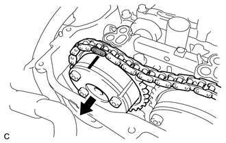
*a Narrow *b Wide Separate the chain sub-assembly from the camshaft timing gear assembly, and turn the camshaft timing gear assembly approximately 180°.
-
Remove the camshaft timing gear assembly.
Note
Do not disassemble the camshaft timing gear assembly.
-
-
REMOVE CAMSHAFT BEARING CAP
-
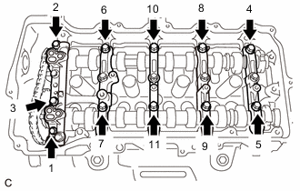
Remove the 11 bolts in several steps in the order shown in the illustration.
-
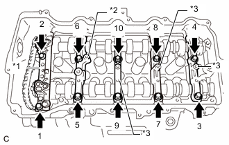
*1 No. 1 Camshaft Bearing Cap *2 No. 2 Camshaft Bearing Cap *3 No. 3 Camshaft Bearing Cap Remove the 10 bolts in several steps in the order shown in the illustration.
-
Remove the No. 1 camshaft bearing cap, No. 2 camshaft bearing cap and 3 No. 3 camshaft bearing caps.
Tech Tips
Arrange the removed parts in such a way that they can be reinstalled to their original locations.
-
-
REMOVE CAMSHAFT
-
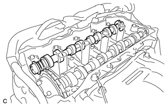
Remove the camshaft from the camshaft housing sub-assembly.
-
-
REMOVE NO. 2 CAMSHAFT
-
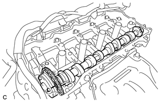
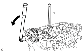
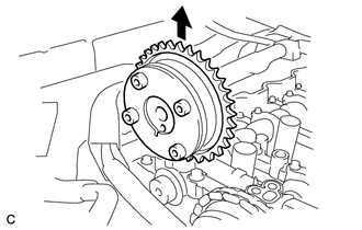
Hold up the chain sub-assembly and remove the No. 2 camshaft from the camshaft housing sub-assembly.
-
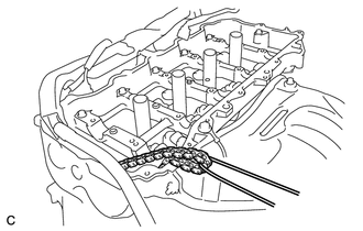
Suspend the chain sub-assembly with a string or equivalent as shown in the illustration.
Note
Be careful not to drop the chain sub-assembly inside the timing chain cover sub-assembly.
-
-
REMOVE CAMSHAFT TIMING EXHAUST GEAR ASSEMBLY
-
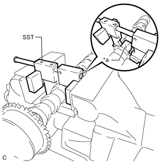
*a Hexagonal Portion Using SST, grip the hexagonal portion, and then secure the SST and No. 2 camshaft in a vise as shown in the illustration.
- SST
- 09212-31010
Note
-
Do not damage the No. 2 camshaft.
-
Never grip areas other than the hexagonal portion, as this may cause damage.
-
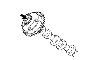
Remove the bolt and camshaft timing exhaust gear assembly.
Note
Do not disassemble the camshaft timing exhaust gear assembly.
-
-
REMOVE OIL CONTROL VALVE FILTER
-
REMOVE NO. 1 CAMSHAFT BEARING
-
REMOVE NO. 2 CAMSHAFT BEARING