AIR CONDITIONING SYSTEM(for Automatic Air Conditioning System) Air Vent Temperature does not Change and Right Vent is Different from Left and Vice Versa (Same Left/Right Temperature Setting)
DESCRIPTION
If the temperature of the air that blows from the left and right front registers differs, even though the same temperature is set for both sides, the following factors may be the cause.
| Symptom | Factor |
|---|---|
| Temperature of outlet air is cooler on left or right side
|
|
| Temperature of outlet air is warmer on left or right side
|
|
-
*1: for 2AR-FE, A25A-FKS
-
*2: for 6AR-FSE, 2GR-FKS
WIRING DIAGRAM
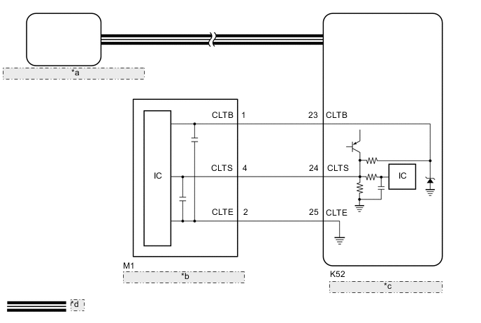
| *a | Air Conditioning Amplifier Assembly |
| *b | Automatic Light Control Sensor |
| *c | Main Body ECU (Multiplex Network Body ECU) |
| *d | CAN Communication Line |
CAUTION / NOTICE / HINT
Note
-
If DTC B1244 is output, troubleshoot for DTC B1244 first.
w/ Automatic Headlight Beam Level Control System: Click here
w/o Automatic Headlight Beam Level Control System: Click here
-
The air conditioning system uses the CAN communication system. Inspect the communication functions by following How to Proceed with Troubleshooting. Troubleshoot the air conditioning system after confirming that the communication systems are functioning properly.
PROCEDURE
-
CHECK WHEN MALFUNCTION OCCURS
Result Result Proceed to When using cooling function A When using heater function B
B 
BLEED AIR FROM COOLING SYSTEM Click here
A 
-
PERFORM REFRIGERANT SHORTAGE CHECK
-
Connect the GTS to the DLC3.
-
Turn the ignition switch to ON.
-
Turn the GTS on.
-
Enter the following menus: Body Electrical / Air Conditioner / Utility / Refrigerant Gas Volume Check.
Body Electrical > Air Conditioner > UtilityTester Display Refrigerant Gas Volume Check -
Check that the following conditions are met and perform the refrigerant shortage check according to the display on the GTS.
Measurement Condition: Item Condition A/C switch On Ambient temperature* 0 to 49°C (32 to 120°F) Blower speed HI *: If the ambient temperature is not within the range shown, do not perform this check.
Result Result Amount of Refrigerant Refrigerant correct Correct Refrigerant shortage Insufficient OK "Refrigerant correct" is displayed on the GTS. Result Proceed to OK NG
NG 
CHARGE SYSTEM WITH REFRIGERANT Click here
OK
-
-
PERFORM ACTIVE TEST USING GTS
-
Connect the GTS to the DLC3.
-
Turn the ignition switch to ON.
-
Turn the GTS on.
-
Enter the following menus: Body Electrical / Air Conditioner / Active Test.
-
Perform the Active Test according to the display on the GTS.
Body Electrical > Air Conditioner > Active TestTester Display Measurement Item Control Range Diagnostic Note Air Mix Servo Targ Pulse(D) No. 1 air conditioning radiator damper servo sub-assembly (driver side air mix) pulse Min.: 128
Max.: 383
-
Operates between 165 to 257 pulses
for LHD:
-
Operates between 255 to 347 pulses
for RHD:
Air Mix Servo Targ Pulse(P) No. 1 air conditioning radiator damper servo sub-assembly (front passenger side air mix) pulse Min.: 128
Max.: 383
-
Operates between 255 to 347 pulses
for LHD:
-
Operates between 165 to 257 pulses
for RHD:
Rear Air Mix Servo Targ Pulse No. 3 air conditioning radiator damper servo sub-assembly pulse Min.: 128
Max.: 383
-
Operates between 165 to 257 pulses
-
*
-
*: for 3 Zone Type
Body Electrical > Air Conditioner > Active TestTester Display Air Mix Servo Targ Pulse(D)
Body Electrical > Air Conditioner > Active TestTester Display Air Mix Servo Targ Pulse(P)
Body Electrical > Air Conditioner > Active TestTester Display Rear Air Mix Servo Targ Pulse OK Each damper servo motor operates. Result Proceed to OK NG -
NG
GO TO DTC TROUBLESHOOTING PROCEDURE FOR MALFUNCTIONING DAMPER SERVO MOTOR Click here
OK
-
-
CHECK HARNESS AND CONNECTOR (AUTOMATIC LIGHT CONTROL SENSOR - MAIN BODY ECU (MULTIPLEX NETWORK BODY ECU))
-
Disconnect the M1 automatic light control sensor connector.
-
Disconnect the K52 main body ECU (multiplex network body ECU) connector.
-
Measure the resistance according to the value(s) in the table below.
Standard Resistance Tester Connection Condition Specified Condition M1-1 (CLTB) - K52-23 (CLTB) Always Below 1 Ω M1-2 (CLTE) - K52-25 (CLTE) Always Below 1 Ω M1-4 (CLTS) - K52-24 (CLTS) Always Below 1 Ω M1-1 (CLTB) or K52-23 (CLTB) - Other terminals and body ground Always 10 kΩ or higher M1-2 (CLTE) or K52-25 (CLTE) - Other terminals and body ground Always 10 kΩ or higher M1-4 (CLTS) or K52-24 (CLTS) - Other terminals and body ground Always 10 kΩ or higher Result Proceed to OK NG
NG
REPAIR OR REPLACE HARNESS OR CONNECTOR
OK
-
-
INSPECT AUTOMATIC LIGHT CONTROL SENSOR
-
Remove the automatic light control sensor.
-
Inspect the automatic light control sensor.
Result Proceed to OK NG
OK
INSPECT REFRIGERANT PRESSURE WITH MANIFOLD GAUGE SET Click here
NG
REPLACE AUTOMATIC LIGHT CONTROL SENSOR Click here
-
-
BLEED AIR FROM COOLING SYSTEM
-
Bleed air from cooling system.
for 2AR-FE: Click here
for A25A-FKS: Click here
for 6AR-FSE: Click here
for 2GR-FKS: Click here
Result Proceed to NEXT
NEXT
-
-
CHECK OPERATION (AIR CONDITIONING SYSTEM)
-
Set the same temperature for the left and right sides and check that the air that blows from the left and right front registers is the same temperature.
OK The air from the left and right front registers is the same temperature. Result Proceed to OK NG
OK
END (MALFUNCTION DUE TO AIR IN COOLING SYSTEM)
NG
-
-
PERFORM ACTIVE TEST USING GTS
-
Connect the GTS to the DLC3.
-
Turn the ignition switch to ON.
-
Turn the GTS on.
-
Enter the following menus: Body Electrical / Air Conditioner / Active Test.
-
Perform the Active Test according to the display on the GTS.
Body Electrical > Air Conditioner > Active TestTester Display Measurement Item Control Range Diagnostic Note Air Mix Servo Targ Pulse(D) No. 1 air conditioning radiator damper servo sub-assembly (driver side air mix) pulse Min.: 128
Max.: 383
-
Operates between 165 to 257 pulses
for LHD:
-
Operates between 255 to 347 pulses
for RHD:
Air Mix Servo Targ Pulse(P) No. 1 air conditioning radiator damper servo sub-assembly (front passenger side air mix) pulse Min.: 128
Max.: 383
-
Operates between 255 to 347 pulses
for LHD:
-
Operates between 165 to 257 pulses
for RHD:
Rear Air Mix Servo Targ Pulse No. 3 air conditioning radiator damper servo sub-assembly pulse Min.: 128
Max.: 383
-
Operates between 165 to 257 pulses
-
*
-
*: for 3 Zone Type
Body Electrical > Air Conditioner > Active TestTester Display Air Mix Servo Targ Pulse(D)
Body Electrical > Air Conditioner > Active TestTester Display Air Mix Servo Targ Pulse(P)
Body Electrical > Air Conditioner > Active TestTester Display Rear Air Mix Servo Targ Pulse OK Each damper servo motor operates. Result Proceed to OK NG -
OK
REPLACE HEATER RADIATOR UNIT SUB-ASSEMBLY Click here
NG
GO TO DTC TROUBLESHOOTING PROCEDURE FOR MALFUNCTIONING DAMPER SERVO MOTOR Click here
-