AUDIO AND VISUAL SYSTEM(for 8 Speakers), Diagnostic DTC:B158F
| DTC Code | DTC Name |
|---|---|
| B158F | AV Signal Stoppage (Low Battery Voltage) |
DESCRIPTION
This DTC is stored when a video or audio signal is interrupted due to battery voltage input to the radio receiver assembly dropping temporarily.
| DTC No. | Detection Item | DTC Detection Condition | Trouble Area |
|---|---|---|---|
| B158F | AV Signal Stoppage (Low Battery Voltage) | A video or audio signal is interrupted when the battery voltage drops |
|
WIRING DIAGRAM
-
w/ Stop and Start System
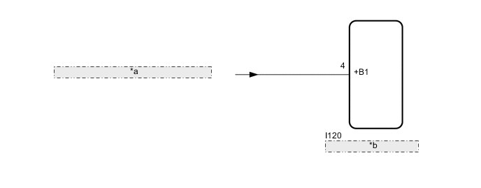
*a from Eco Run Vehicle Converter Assembly *b Radio Receiver Assembly -
w/o Stop and Start System
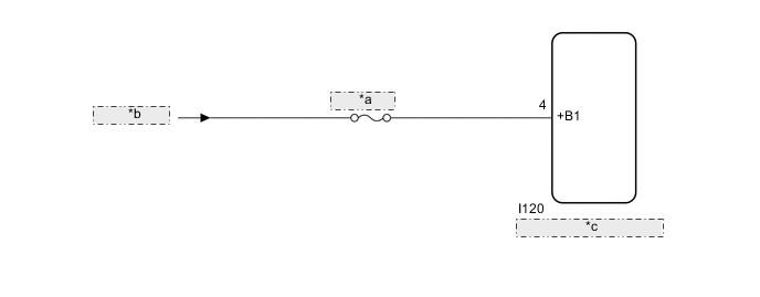
*a ECU-B NO.5 *b from Battery *c Radio Receiver Assembly
CAUTION / NOTICE / HINT
Note
Inspect the fuses for circuits related to this system before performing the following procedure.
Tech Tips
w/ Stop and Start System:
The audio and visual system troubleshooting procedure is based on the premise that the stop and start system is operating normally. Check the audio and visual system first before troubleshooting the audio and visual system.
PROCEDURE
-
CHECK VEHICLE SIGNAL (OPERATION CHECK)
-
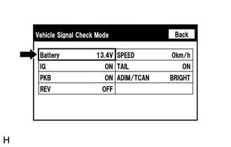
Enter the "Vehicle Signal Check Mode" screen. Refer to Check Vehicle Signal in Operation Check.
-
Measure the battery voltage.
Standard voltage 11 to 14 V Tech Tips
This display is updated once per second.
Result Proceed to OK NG
NG 
CHECK HARNESS AND CONNECTOR (RADIO RECEIVER ASSEMBLY - BATTERY) Click here
OK 
-
-
CHECK DTC
-
Clear the DTCs.
Body Electrical > Navigation System > Clear DTCs -
Recheck for DTCs and check that no DTCs are output.
Body Electrical > Navigation System > Trouble CodesOK No DTCs are output. Result Proceed to OK NG
OK 
USE SIMULATION METHOD TO CHECK Click here
NG
REPLACE RADIO RECEIVER ASSEMBLY Click here
-
-
CHECK HARNESS AND CONNECTOR (RADIO RECEIVER ASSEMBLY - BATTERY)
-
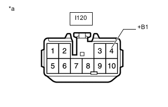
*a Front view of wire harness connector
(to Radio Receiver Assembly)
Disconnect the radio receiver assembly connector.
-
Measure the voltage according to the value(s) in the table below.
Standard Voltage w/ Stop and Start System Tester Connection Condition Specified Condition I120-4 (+B1) - Body ground Always 10.5 to 16 V w/o Stop and Start System Tester Connection Condition Specified Condition I120-4 (+B1) - Body ground Always 11 to 14 V Result Proceed to OK NG
OK
REPLACE RADIO RECEIVER ASSEMBLY Click here
NG
REPAIR OR REPLACE HARNESS OR CONNECTOR
-