AIR CONDITIONING SYSTEM ECO Switch Circuit
DESCRIPTION
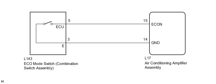
When the ECO mode switch (combination switch assembly) is turned on, the air conditioning amplifier assembly receives an ECO switch ON signal and controls the air conditioning to enhance fuel efficiency.
WIRING DIAGRAM
PROCEDURE
-
READ VALUE USING GTS
-
Connect the GTS to the DLC3.
-
Turn the power switch on (IG).
-
Turn the GTS on.
-
Enter the following menus: Body Electrical / Air Conditioner / Data Test.
-
Check the values by referring to the table below.
Air Conditioner Tester Display Measurement Item/Range Control Range Diagnostic Note ECO Switch ECO switch /
OFF or ON
ECO mode switch (combination switch assembly) not operated: OFF
(when switch is not pressed)
- ECO mode switch (combination switch assembly) operated: ON
(when switch is pressed)
OK ECO mode switch (combination switch assembly) condition displayed on the GTS changes with the actual switch operation.
OK 
PROCEED TO NEXT SUSPECTED AREA SHOWN IN PROBLEM SYMPTOMS TABLE Click here
NG 
-
-
INSPECT ECO MODE SWITCH (COMBINATION SWITCH ASSEMBLY)
-
Remove the ECO mode switch (combination switch assembly) Click here.
-
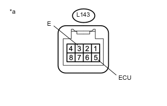
Text in Illustration *a Component without harness connected
ECO Mode Switch (Combination Switch Assembly)
Measure the resistance according to the value(s) in the table below.
Standard Resistance Tester Connection Condition Specified Condition L143-5 (ECU) - L143-3 (E) ECO mode switch (combination switch assembly) off
(when switch is not pressed)
10 kΩ or higher L143-5 (ECU) - L143-3 (E) ECO mode switch (combination switch assembly) on
(when switch is pressed)
Below 1 Ω
NG
REPLACE ECO MODE SWITCH (COMBINATION SWITCH ASSEMBLY) Click here
OK
-
-
CHECK HARNESS AND CONNECTOR (ECO MODE SWITCH (COMBINATION SWITCH ASSEMBLY) - AIR CONDITIONING AMPLIFIER)
-
Disconnect the L17 air conditioning amplifier assembly connector.
-
Measure the resistance according to the value(s) in the table below.
Standard Resistance Tester Connection Condition Specified Condition L17-15 (ECOS) - L143-5 (ECU) Always Below 1 Ω L17-15 (ECOS) - Body ground Always 10 kΩ or higher L17-14 (GND) - L143-3 (E) Always Below 1 Ω L17-14 (GND) - Body ground Always 10 kΩ or higher
OK
REPLACE AIR CONDITIONING AMPLIFIER ASSEMBLY Click here
NG
REPAIR OR REPLACE HARNESS OR CONNECTOR
-