DIFFERENTIAL CASE DISASSEMBLY
PROCEDURE
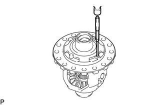
REMOVE FRONT DIFFERENTIAL CASE FRONT TAPERED ROLLER BEARING
-
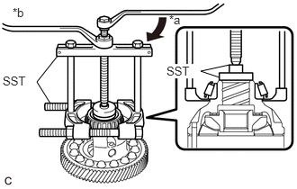
Using SST, remove the front differential case front tapered roller bearing from the front No. 1 differential case sub-assembly.
09950-00020
09950-00030
09950-40011
09957-04010
09950-60010
09951-00560
Table 1. Text in Illustration *a
Turn
*b
Hold
-
REMOVE FRONT DIFFERENTIAL CASE REAR TAPERED ROLLER BEARING
-
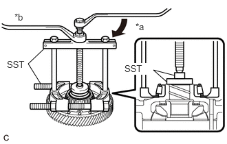
Using SST, remove the front differential case rear tapered roller bearing from the front No. 1 differential case sub-assembly.
09950-00020
09950-00030
09950-40011
09957-04010
09950-60010
09951-00490
Table 2. Text in Illustration *a
Turn
*b
Hold
-
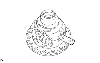
REMOVE FRONT DIFFERENTIAL RING GEAR
-
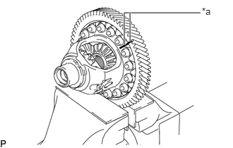
Put matchmarks on the front differential ring gear and front No. 1 differential case sub-assembly.
Table 3. Text in Illustration *a
Matchmark
-
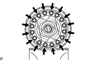
Remove the 16 bolts.
Using a plastic-faced hammer, remove the front No. 1 differential case sub-assembly from the front differential ring gear.
-
INSPECT FRONT NO. 1 DIFFERENTIAL CASE SUB-ASSEMBLY
REMOVE FRONT DIFFERENTIAL PINION SHAFT STRAIGHT PIN
-
Using a 5 mm pin punch and hammer, tap out the front differential pinion shaft straight pin from the front No. 1 differential case sub-assembly.
-
REMOVE FRONT NO. 1 DIFFERENTIAL PINIONSHAFT
-
Remove the front No. 1 differential pinion shaft from the front No. 1 differential case sub-assembly.
-
INSPECT FRONT DIFFERENTIAL PINION BACKLASH
REMOVE FRONT DIFFERENTIAL SIDE GEAR
Set SST as shown in the illustration and tighten it.
09528-52010
09953-05010
09528-05010
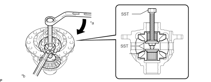
Table 4. Text in Illustration *a
Turn
*b
Hold
Note:Do not overtighten SST, as doing so will damage the front differential side gear, conical spring, front differential side gear thrust washer and front No. 1 differential case sub-assembly.
Tip:Tighten SST until there is a clearance between the front differential pinion and front differential side gear.
When removing the front differential pinion, do not overtighten SST, as it is necessary to rotate the front differential side gear.
-
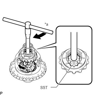
Install SST as shown in the illustration, rotate the front differential side gear, and then remove the 2 front differential pinions and 2 front differential pinion thrust washers from the front No. 1 differential case sub-assembly.
09528-52010
09528-05030
Table 5. Text in Illustration *a
Turn
Note:Do not drop the front differential pinion and front differential pinion thrust washer.
-
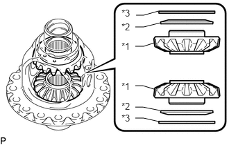
Remove SST from the front No. 1 differential case sub-assembly, and then remove the 2 front differential side gears, 2 front differential side gear thrust washers and 2 conical springs from the front No. 1 differential case sub-assembly.
Table 6. Text in Illustration *1
Front Differential Side Gear
*2
Conical Spring
*3
front differential side gear thrust washer
Note:Do not drop the front differential side gear, front differential side gear thrust washer and conical spring.