CYLINDER HEAD REPLACEMENT
PROCEDURE
REPLACE INTAKE VALVE GUIDE BUSH
Heat the cylinder head sub-assembly to between 80 and 100°C (176 and 212°F).
Place the cylinder head sub-assembly on wooden blocks.
-
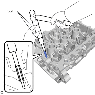
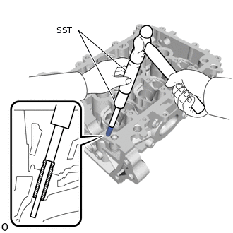
Using SST and a hammer, tap out the intake valve guide bush.
09201-10000
09201-01050
09950-70010
09951-07100
-
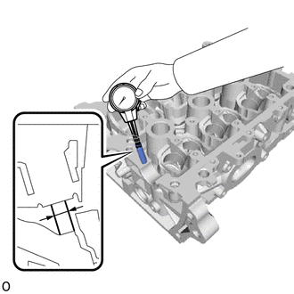
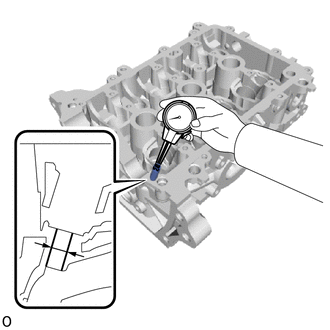
Using a caliper gauge, measure the intake valve guide bush bore diameter of the cylinder head sub-assembly.
Standard Bush Bore Diameter
9.685 to 9.706 mm (0.3813 to 0.3821 in.)
New Guide Bush Selection Chart (STD or O/S 0.05)
Bush Size
Bush Bore Diameter
STD
9.727 to 9.738 mm (0.3830 to 0.3834 in.)
O/S 0.05
9.777 to 9.788 mm (0.3849 to 0.3854 in.)
Tip:If the bush bore diameter of the cylinder head sub-assembly is greater than 9.706 mm (0.3821 in.), machine the bush bore to a dimension of 9.735 to 9.756 mm (0.3833 to 0.3841 in.) to install an O/S 0.05 valve guide bush.
Heat the cylinder head sub-assembly to between 80 and 100°C (176 and 212°F).
Place the cylinder head sub-assembly on wooden blocks.
-
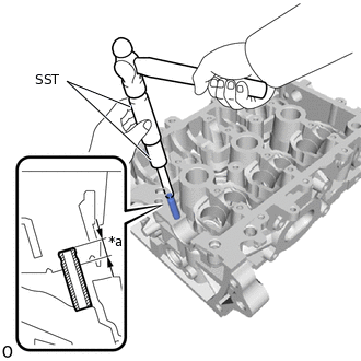
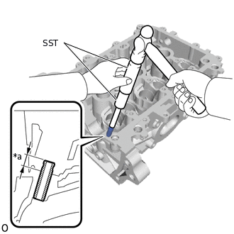
*a
Protrusion Height
Using SST and a hammer, tap in a new intake valve guide bush to the specified protrusion height.
09201-10000
09201-01050
09950-70010
09951-07100
Standard Protrusion Height
9.8 to 10.4 mm (0.3858 to 0.4094 in.)
-
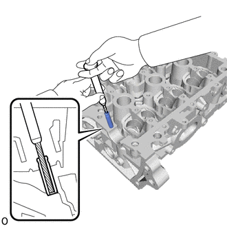
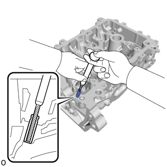
Using a sharp 5.5 mm reamer, ream the intake valve guide bush to obtain the standard clearance between the intake valve guide bush and valve stem.
Standard Oil Clearance
0.025 to 0.060 mm (0.000984 to 0.00236 in.)
REPLACE EXHAUST VALVE GUIDE BUSH
Heat the cylinder head sub-assembly to between 80 and 100°C (176 and 212°F).
Place the cylinder head sub-assembly on wooden blocks.
-
Using SST and a hammer, tap out the exhaust valve guide bush.
09201-10000
09201-01050
09950-70010
09951-07100
-
Using a caliper gauge, measure the exhaust valve guide bush bore diameter of the cylinder head sub-assembly.
Standard Bush Bore Diameter
9.685 to 9.706 mm (0.3813 to 0.3821 in.)
New Guide Bush Selection Chart (STD or O/S 0.05)
Bush Size
Bush Bore Diameter
STD
9.727 to 9.738 mm (0.3830 to 0.3834 in.)
O/S 0.05
9.777 to 9.788 mm (0.3849 to 0.3854 in.)
Tip:If the bush bore diameter of the cylinder head sub-assembly is greater than 9.706 mm (0.3821 in.), machine the bush bore to a dimension of 9.735 to 9.756 mm (0.3833 to 0.3841 in.) to install an O/S 0.05 valve guide bush.
Heat the cylinder head sub-assembly to between 80 and 100°C (176 and 212°F).
Place the cylinder head sub-assembly on wooden blocks.
-
*a
Protrusion Height
Using SST and a hammer, tap in a new exhaust valve guide bush to the specified protrusion height.
09201-10000
09201-01050
09950-70010
09951-07100
Standard Protrusion Height
9.4 to 10.0 mm (0.3701 to 0.3937 in.)
-
Using a sharp 5.5 mm reamer, ream the exhaust valve guide bush to obtain the standard oil clearance between the exhaust valve guide bush and valve stem.
Standard Oil Clearance
0.025 to 0.060 mm (0.000984 to 0.00236 in.)
REPLACE RING PIN
Note:It is not necessary to remove the ring pins unless they are being replaced.
-
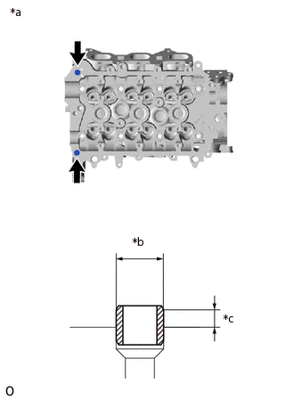
*a
Upper Side
*b
Width
*c
Protrusion Height
Remove the 2 ring pins.
Using a plastic hammer, tap in 2 new ring pins to the specified protrusion height.
Standard Ring Pin
Item
Width
Protrusion Height
Ring pin
11.0 mm (0.433 in.)
4.5 to 5.5 mm (0.177 to 0.217 in.)
-
REPLACE STUD BOLT
Note:If any of the stud bolts is deformed or the threads are damaged, replace it.
Using an E8 "TORX" socket, install a new stud bolt.
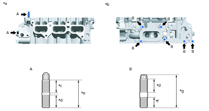
*a
Intake Side
*b
Exhaust Side
*c
14.0 mm (0.551 in.)
*d
13.0 mm (0.512 in.)
*e
29.0 mm (1.14 in.)
*f
10.5 mm (0.41 in.)
*g
33.5 mm (1.32 in.)
-
-
7.5 N*m
76 kgf*cm
66 in.*lbf