SFI SYSTEM, Diagnostic DTC:P0341,P0342 and P0343
| DTC Code | DTC Name |
|---|---|
| P0341 | Camshaft Position Sensor "A" Circuit Range / Performance (Bank 1 or Single Sensor) |
| P0342 | Camshaft Position Sensor Circuit Low Input |
| P0343 | Camshaft Position Sensor Circuit High Input |
DESCRIPTION
The camshaft position sensor (G signal) consists of a magnet and MRE (Magnet Resistance Element).
The intake camshaft has a timing rotor for the camshaft position sensor. When the camshaft rotates, changes occur in the air gaps between the timing rotor and MRE, which affects the magnetic field. As a result, the resistance of the MRE material fluctuates. The camshaft position sensor converts the camshaft rotation data to pulse signals, uses the pulse signals to determine the camshaft angle, and sends it to the ECM. Then the ECM uses this data to control fuel injection duration, fuel injection timing and Variable Valve Timing (VVT) system.
DTC No. |
Detection Item |
DTC Detection Condition |
Trouble Area |
MIL |
Memory |
|---|---|---|---|---|---|
P0341 |
Camshaft Position Sensor "A" Circuit Range / Performance (Bank 1 or Single Sensor) |
Teeth of camshaft timing rotor or camshaft position cannot be detected correctly for 5 crankshaft revolutions (1 trip detection logic). |
|
Comes on |
DTC stored |
P0342 |
Camshaft Position Sensor Circuit Low Input |
Camshaft position sensor output stays low (1 trip detection logic). |
|
Comes on |
DTC stored |
P0343 |
Camshaft Position Sensor Circuit High Input |
Camshaft position sensor output stays high (1 trip detection logic). |
|
Comes on |
DTC stored |
WIRING DIAGRAM
Refer to DTC P0335.
CONFIRMATION DRIVING PATTERN
These DTCs are detected when the engine is running or the engine cranks 100 revolutions or more.
CAUTION / NOTICE / HINT
After replacing the ECM, perform idle learning.
If any DTCs related to the manifold absolute pressure sensor, accelerator pedal sensor assembly and camshaft position sensor are output simultaneously, inspect the VC circuit of each component.
Read freeze frame data using the GTS. Freeze frame data records the engine condition when malfunctions are detected. When troubleshooting, freeze frame data can help determine if the vehicle was moving or stationary, if the engine was warmed up or not, if the air fuel ratio was lean or rich, and other data from the time the malfunction occurred.
PROCEDURE
CHECK TERMINAL VOLTAGE (POWER SOURCE OF CAMSHAFT POSITION SENSOR)
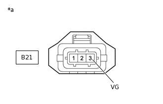
*a
Front view of wire harness connector
(to Camshaft Position Sensor)
Disconnect the camshaft position sensor connector.
Turn the ignition switch to ON.
Measure the voltage according to the value(s) in the table below.
Standard Voltage
Tester Connection
Condition
Specified Condition
B21-3 (VG) - Body ground
Ignition switch ON
4.5 to 5.5 V
Result
Proceed to
OK
NG
NG CHECK HARNESS AND CONNECTOR (CAMSHAFT POSITION SENSOR - ECM)Click here
CHECK HARNESS AND CONNECTOR (CAMSHAFT POSITION SENSOR - ECM)
Disconnect the camshaft position sensor connector.
Disconnect the ECM connector.
Measure the resistance according to the value(s) in the table below.
Standard Resistance
Tester Connection
Condition
Specified Condition
B21-2 (G1) - B31-82 (G1)
Always
Below 1 Ω
B21-1 (G-) - B31-114 (G-)
Always
Below 1 Ω
B21-2 (G1) or B31-82 (G1) - Body ground
Always
10 kΩ or higher
B21-1 (G-) or B31-114 (G-) - Body ground
Always
10 kΩ or higher
Result
Proceed to
OK
NG
NG REPAIR OR REPLACE HARNESS OR CONNECTOR
CHECK CAMSHAFT POSITION SENSOR INSTALLATION
Check the camshaft position sensor installation condition.
OK
Camshaft position sensor is installed correctly.
Result
Proceed to
OK
NG
INSPECT CAMSHAFT
Inspect the teeth of the camshaft.
OK
The teeth do not have any cracks or deformation.
Result
Proceed to
OK
NG
REPLACE CAMSHAFT POSITION SENSOR
Replace the camshaft position sensor.
Result
Proceed to
NEXT
CHECK WHETHER DTC OUTPUT RECURS (DTC P0341, P0342 OR P0343)
Connect the GTS to the DLC3.
Turn the ignition switch to ON.
Turn the GTS on.
Clear the DTCs.
Powertrain > Engine and ECT > Clear DTCs
Turn the ignition switch off and wait for at least 30 seconds.
Start the engine.
Turn the GTS on.
Stop the engine and wait for at least 10 seconds.
Enter the following menus: Powertrain / Engine and ECT / Trouble Codes.
Read the DTCs.
Powertrain > Engine and ECT > Trouble Codes
Result
Result
Proceed to
DTCs are not output
A
DTC P0341, P0342 or P0343 is output
B
A END
CHECK HARNESS AND CONNECTOR (CAMSHAFT POSITION SENSOR - ECM)
Disconnect the camshaft position sensor connector.
Disconnect the ECM connector.
Measure the resistance according to the value(s) in the table below.
Standard Resistance
Tester Connection
Condition
Specified Condition
B21-3 (VG) - B31-113 (VCG1)
Always
Below 1 Ω
B21-3 (VG) or B31-113 (VCG1) - Body ground
Always
10 kΩ or higher
Result
Proceed to
OK
NG
NG REPAIR OR REPLACE HARNESS OR CONNECTOR