CVT SYSTEM
-
FUNCTION OF MAIN COMPONENTS
Component Function CVT Fluid Warmer (Transmission Oil Cooler) Warms up the CVT fluid quickly. Torque Converter Assembly
-
Transmits engine power to the transaxle.
-
Increases engine torque.
Oil Pump Assembly Provides oil pressure necessary for the transaxle operation. Forward Clutch Connects the input shaft with the sun gear. Reverse Brake Keeps the planetary carrier stationary. Shift Solenoid Valve DS1 Controls the fluid flow volume to the primary pulley in accordance with the vehicle speed and accelerator pedal position (speed control during acceleration). Shift Solenoid Valve DS2 Controls the fluid flow volume from the primary pulley in accordance with the vehicle speed and accelerator pedal position (speed control during deceleration). Shift Solenoid Valve DSU Controls the engagement oil pressure of the lock-up clutch. Shift Solenoid Valve SL Switches the operation of the solenoid valve SLS. Shift Solenoid Valve SLS
-
Controls the oil pressure of the secondary pulley.
-
Controls the engagement oil pressure of the forward clutch and reverse brake.
Transmission Revolution Sensor (NIN) Detects the primary pulley speed (input speed). Transmission Revolution Sensor (NOUT) Detects the secondary pulley speed (output speed). Transmission Revolution Sensor (NT) Detects the forward clutch drum speed. CVT Fluid Temperature Sensor Detects the CVT fluid temperature. Oil Pressure Sensor Detects the steel belt clamping force. Park/Neutral Position Switch Assembly Detects the shift lever position. Transmission Control Switch
-
Detects that the shift lever is in M.
-
Detects the driver's upshift and downshift operations when the shift lever is in M.
Drive Module Switch Assembly Sport Mode Switch Turns the Sport mode on and off. ECO Mode Switch Turns the ECO mode on and off. ECM
-
Controls engine output and the electronic control of the CVT system.
-
Makes a diagnosis and memorizes the failed section when the ECM detects a malfunction.
Air Conditioning Amplifier Assembly
-
Transmits the operating state of the air conditioning system to the ECM.
-
Outputs the ECO mode signal to the ECM.
Driving Support ECU Assembly*1 Sends the information about the operation conditions of the dynamic radar cruise control system to the ECM. Combination Meter Assembly Sport Mode Indicator Light*2 Illuminates when Sport mode is active. ECO Mode Indicator Light*2 Illuminates when ECO mode is active. MIL Illuminates or blinks to alert the driver that the ECM has detected a malfunction. Master Warning Light*3 Warns the driver by lighting up when a message is shown on the multi-information display. Multi-information Display
-
Displays the drive mode.*3
-
Displays the shift lever position.
-
Displays the gear step (M1 to M7).
Buzzer
-
Sounds when the shift-down operation is rejected.
-
Warns the driver by sounding when a message is shown on the multi-information display.*3
*1: Models with dynamic radar cruise control system
*2: Models with analog type combination meter assembly
*3: Models with Optitron type combination meter assembly
-
-
SYSTEM CONTROL
Electronic Control of CVT Control Outline Engine - CVT Integrated Control Performs coordinate control of the CVT system and engine control system to ensure both smooth and powerful driving that excels in shift response and fuel economy. Pulley Ratio Control Automatic Shift Control Optimally controls the pulley ratio and shifting speed to suit the driver's intentions and driving conditions based on signals from various sensors and switches. Acceleration Improvement Control Deceleration Improvement Control 7-speed Sport Sequential Shiftmatic Shift Control in Uphill/Downhill Traveling Controls to restrict the upshift or to provide appropriate engine braking by using the ECM to determine whether the vehicle is traveling uphill or downhill. Lock-up Control The ECM sends a current to shift solenoid valve DSU based on the throttle position sensor signal and vehicle speed signal, and engages or disengages the lock-up clutch.
-
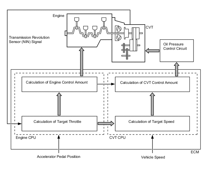
Engine - CVT Integrated Control
-
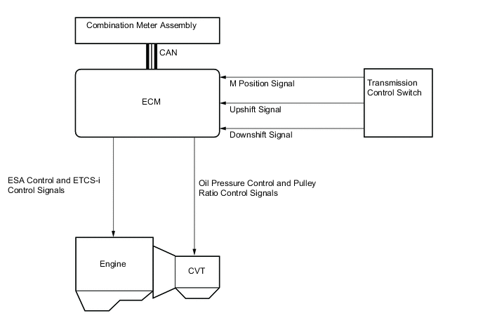
To perform fine-tuned control in accordance with driving conditions, various signals are exchanged between the engine control system and the CVT system. As a result, both smooth and powerful driving that excels in shift response and fuel economy has been achieved.
-
-
Pulley Ratio Control
-
The ECM judges the driving conditions through each input signal and selects the optimal control to achieve driving which meets the driver's intentions.
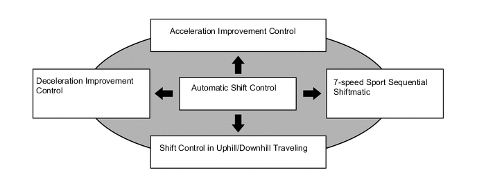
Pulley Ratio Control Control Feature Automatic Shift Control Smoothly achieves fuel efficiency. Acceleration Improvement Control Achieves a direct and linear acceleration feeling. Deceleration Improvement Control
-
Ensures engine braking during deceleration.
-
Improves re-acceleration response after deceleration.
7-speed Sport Sequential Shiftmatic Achieves highly responsive shifting feedback. Shift Control in Uphill/Downhill Traveling
-
Ensures drive force when driving uphill.
-
Ensures engine braking when driving downhill.
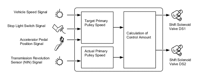
-
The ECM calculates the target primary pulley speed in accordance with the accelerator pedal position signal, vehicle speed signal and stop light switch signal, in order to attain an optimal pulley ratio and shifting speed. To allow the actual primary pulley speed (acquired from the primary speed sensor) to match the target primary pulley speed, the ECM actuates the shift solenoid valves DS1 and DS2 in order to control the inflow and outflow volume of the line pressure to and from the primary pulley. As a result, optimal pulley ratio and shifting speed have been achieved.
-
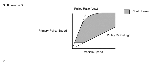
Automatic Shift Control
-
When the shift lever is in D, the system performs engine integrated control to optimize fuel economy characteristics and driving performance.
-
Through the wide shifting range and lock-up control, which can be regulated by low vehicle speed, quietness and low fuel consumption are achieved by decreasing the engine speed as far as possible.
-
Throttle characteristics and shifting characteristics are utilized to flexibly control driving speed in response to the acceleration operation, thus achieving smooth driving without shifting shock.
-
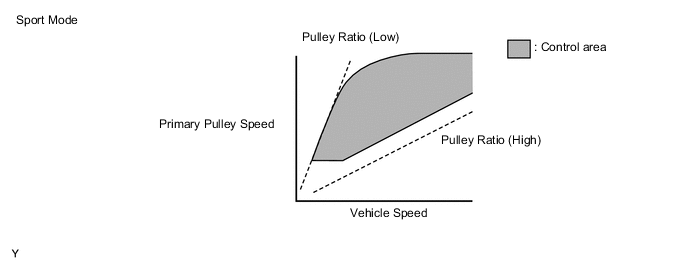
The Sport mode limits the gear step for the acceleration side and maintains the primary pulley speed at high speeds. This produces a moderate engine braking force and provides an excellent shift response.
-
-
Acceleration Improvement Control
-
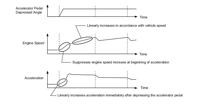
The system determines the driver's acceleration request based on the vehicle speed and the changes in the accelerator pedal position. When the system determines this request, it changes the shift characteristic into one in which the engine speed and vehicle speed increase linearly. This improves the acceleration feeling.
-
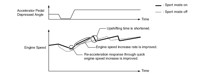
When Sport mode is on, upshifting time is shortened and engine speed increase rate is improved, thus giving a sportier setting compared to when Sport mode is off.
-
-
Deceleration Improvement Control
-
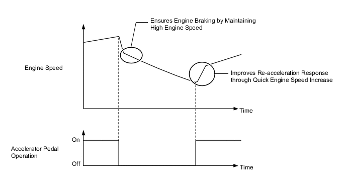
During deceleration, the pulley ratio is determined and a high engine speed is maintained, thus ensuring adequate engine braking.
-
Engine control, which generates driving force quickly, is conducted during re-acceleration.
-
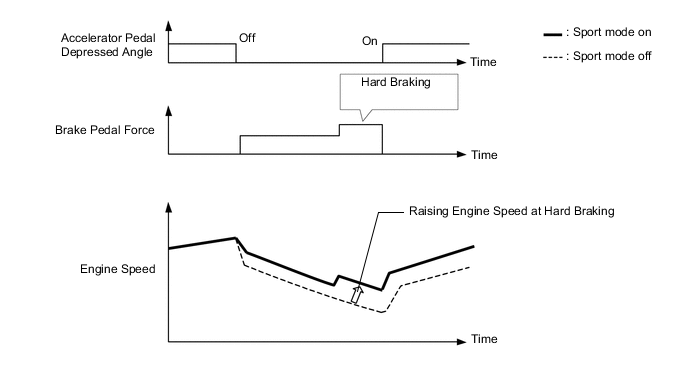
When decelerating with Sport mode on, the pulley ratio is fixed in the lower ratio side to achieve a quicker deceleration response and stronger engine braking force compared to when Sport mode is off. In addition, a higher brake pedal force is caused by increasing engine speed when braking hard, and braking downshift control which generates a quick drive force during re-acceleration is used.
-
-
7-speed Sport Sequential Shiftmatic
-
The 7-speed sport sequential shiftmatic is designed to allow the driver to switch the gear step. After moving the shift lever to M, the driver can select the desired gear step by moving the shift lever to "+" (forward) or "-" (backward). Thus, the driver is able to shift gears with a manual-like feel.
-
Through the engine-CVT integrated control, pulley ratio and engine torque which corresponds to shifting speed are finely controlled, thus improving shifting response and achieving a reduction in shifting shock.
-
When the shift lever is in M, this system automatically upshifts or downshifts under the following conditions:
Condition System Control Engine is under-revving. 1 step downshift Engine is over-revving. 1 step upshift -
When the vehicle is stopped while the shift lever is in M, the transaxle automatically downshifts to M1.
-
When the accelerator pedal is fully depressed and a kickdown operation is performed, a downshift to a gear step determined according to the vehicle speed is performed.
-
The ECM will restrict the changing of the gear step if it detects a malfunction in the CVT system.
-
If the vehicle speed and engine speed exceed or go below a preset level in response to the driver's downshift operation request, changing the gear step will be prohibited. In this case, the buzzer in the combination meter will sound to alert the driver.
-
High response sequential shiftmatic control is used for shift shock reduction and improved shifting response during shift operation. The control cooperates with Electronic Throttle Control System-intelligent (ETCS-i) and Electronic Spark Advance (ESA) to finely regulate engine torque in accordance with the pulley ratio and shifting speed. As a result, shifting performance with smooth and sharp response has been achieved to shorten the time of shifting considerably.
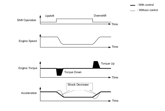
High Response Sequential Shiftmatic Control
-
-
Shift Control in Uphill/Downhill Traveling
-
The ECM determines that the vehicle is driving uphill or downhill based on the accelerator pedal position sensor signal and the vehicle speed signal. During uphill driving, the ECM limits upshift to achieve smooth driving. During downhill driving, the ECM downshifts upon detecting brake pedal operation, in order to provide moderate engine braking.
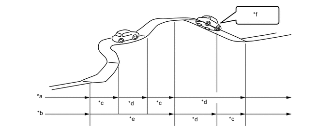
*a Without Control *b With Control *c Downshift *d Upshift *e Restrict Upshift *f Brake Operation -
The actual acceleration calculated from the vehicle speed signal is compared with the reference acceleration (based on level road travel) stored in the ECM to determine uphill or downhill travel.
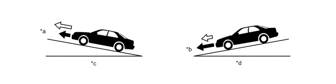
*a Smaller *b Greater *c Uphill *d Downhill 
Actual Acceleration 
Reference Acceleration
-
-
-
Lock-up Control
-
The lock-up operation range has been expanded from that of the previous automatic transaxle, thus enabling control to start from low speeds.
-
The lock-up operation range during deceleration has been expanded to the low-speed range. This expands the fuel cut range and achieves excellent fuel economy.
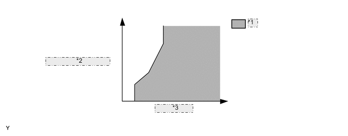
*1 Lock-up on *2 Throttle Opening Angle *3 Vehicle Speed
-
-
-
FAIL-SAFE
-
This function minimizes the loss of operability when any abnormality occurs in any sensor or shift solenoid valve.
-
For details, refer to the Repair Manual.
-
-
DIAGNOSIS
-
When the ECM detects a malfunction, it makes a diagnosis and memorizes the failed section. Furthermore, the MIL in the combination meter illuminates or blinks to inform the driver.
-
At the same time, the Diagnostic Trouble Codes (DTCs) are stored in memory. The DTCs can be read by connecting a Global TechStream (GTS). For details, refer to the Repair Manual.
-