CYLINDER HEAD GASKET REMOVAL
CAUTION / NOTICE / HINT
The necessary procedures (adjustment, calibration, initialization, or registration) that must be performed after parts are removed and installed, or replaced during cylinder head gasket removal/installation are shown below.
| Replaced Part or Performed Procedure | Necessary Procedure | Effect/Inoperative Function when Necessary Procedure not Performed | Link | |
|---|---|---|---|---|
| Battery terminal is disconnected/reconnected | Perform steering sensor zero point calibration | Lane departure alert system (w/ Steering Control) | ||
| Pre-collision system | ||||
| Memorize steering angle neutral point | Parking assist monitor system | |||
| Panoramic view monitor system | ||||
| Replacement of ECM | Vehicle Identification Number (VIN) registration | MIL comes on | ||
| Perform code registration (Immobiliser system) |
|
See Service Bulletin for the registration method. | ||
|
Inspection after repair |
|
||
| Replacement of ECM (If possible, read the transaxle compensation code from the previous ECM) |
Possible | Perform the following procedures in the order shown:
|
|
Click here for U760E Initialization Click here for U760E Registration |
| Impossible | Perform the following procedures in the order shown:
|
|||
| Replacement of ECM*1 | Perform code registration (Immobiliser function) |
|
See Service Bulletin for the registration method. | |
| Replacement of ECM*2 | Perform code registration (Immobiliser system) |
|
See Service Bulletin for the registration method. | |
| Replacement of automatic transaxle fluid | ATF thermal degradation estimate reset | The value of the Data List item "ATF Thermal Degradation Estimate" is not estimated correctly. | ||
| Suspension, tires*3 | Rear television camera assembly optical axis (Back camera position setting) | Parking assist monitor system | Click here for Initialization Click here for Calibration |
|
| Perform headlight ECU sub-assembly LH initialization | Lighting system (EXT) | |||
|
Panoramic view monitor system | Click here for Initialization Click here for Calibration |
||
| Replacement of front bumper assembly | Front television camera view adjustment | |||
| Front wheel alignment adjustment | Perform system variant learning and acceleration sensor zero point calibration. |
|
||
*2: w/o Smart Entry and Start System
*3: The vehicle height changes because of suspension or tire replacement.
PROCEDURE
-
REMOVE TIMING CHAIN COVER SUB-ASSEMBLY
-
REMOVE MANIFOLD STAY
-
REMOVE NO. 2 MANIFOLD STAY
-
REMOVE NO. 1 EXHAUST MANIFOLD HEAT INSULATOR
-
REMOVE EXHAUST MANIFOLD CONVERTER SUB-ASSEMBLY (TWC: Front Catalyst)
-
REMOVE THROTTLE BODY WITH MOTOR ASSEMBLY
-
REMOVE THROTTLE BODY GASKET
-
REMOVE VACUUM SWITCHING VALVE ASSEMBLY (for ACIS)
-
REMOVE FUEL DELIVERY PIPE
-
REMOVE FUEL DELIVERY SPACER
-
REMOVE INJECTOR VIBRATION INSULATOR
-
REMOVE FUEL INJECTOR ASSEMBLY
-
DISCONNECT NO. 2 VENTILATION HOSE
-
REMOVE INTAKE MANIFOLD
-
SET NO. 1 CYLINDER TO TDC/COMPRESSION
-
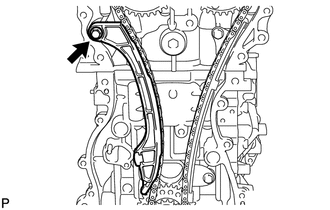
REMOVE TIMING CHAIN GUIDE
-
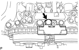
Remove the bolt and timing chain guide.
-
-
REMOVE NO. 1 CHAIN TENSIONER ASSEMBLY
-
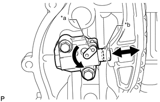
*a Stopper Plate *b Plunger Allow the plunger to extend slightly, and then turn the stopper plate counterclockwise to release the lock. Once the lock is released, push the plunger into the No. 1 chain tensioner assembly.
-
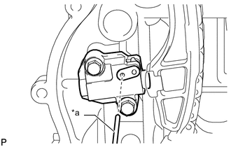
*a Pin Move the stopper plate clockwise to set the lock, and insert a pin into the stopper plate hole.
-
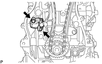
Remove the 2 bolts, No. 1 chain tensioner assembly and gasket.
-
-
REMOVE CHAIN TENSIONER SLIPPER
-
Remove the bolt and chain tensioner slipper.
-
-
REMOVE CHAIN SUB-ASSEMBLY
-
Remove the chain sub-assembly.
-
-
REMOVE NO. 1 CHAIN VIBRATION DAMPER
-
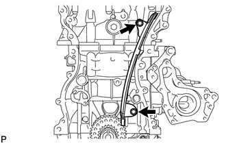
Remove the 2 bolts and No. 1 chain vibration damper.
-
-
REMOVE CAMSHAFT TIMING GEAR ASSEMBLY
-
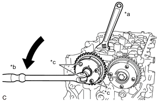
*a Hold *b Turn *c Do not remove Using a wrench to hold the hexagonal portion of the camshaft, remove the bolt and camshaft timing gear assembly.
Note
-
Be careful not to damage the cylinder head sub-assembly or spark plug tube with the wrench.
-
Do not disassemble the camshaft timing gear assembly.
-
Do not remove the other 4 bolts.
-
-
-
REMOVE CAMSHAFT TIMING EXHAUST GEAR ASSEMBLY
-
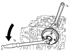
*a Hold *b Turn Using a wrench to hold the hexagonal portion of the No. 2 camshaft, remove the bolt and camshaft timing exhaust gear assembly.
Note
Be careful not to damage the camshaft housing sub-assembly, cylinder head sub-assembly or spark plug tube with the wrench.
-
-
REMOVE CAMSHAFT HOUSING SUB-ASSEMBLY
-
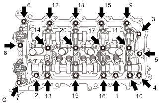
Uniformly loosen and remove the 20 bolts in the order shown in the illustration.
-
Remove the camshaft housing sub-assembly by prying between the cylinder head sub-assembly and camshaft housing sub-assembly with a screwdriver.
Note
Be careful not to damage the contact surfaces of the cylinder head sub-assembly and camshaft housing sub-assembly.
Tech Tips
Tape the screwdriver tip before use.
-
-
REMOVE CAMSHAFT BEARING CAP
-
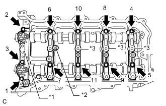
*1 No. 1 Camshaft Bearing Cap *2 No. 2 Camshaft Bearing Cap *3 No. 3 Camshaft Bearing Cap Remove the 11 bolts in the order shown in the illustration.
-
Remove the No. 1 camshaft bearing cap, No. 2 camshaft bearing cap and 3 No. 3 camshaft bearing caps.
Tech Tips
Arrange the removed parts in such a way that they can be reinstalled to their original locations.
-
-
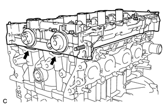
REMOVE OIL CONTROL VALVE FILTER
-
REMOVE NO. 1 CAMSHAFT BEARING
-
REMOVE CAMSHAFT
-
Remove the camshaft from the camshaft housing sub-assembly.
-
-
REMOVE NO. 2 CAMSHAFT
-
Remove the No. 2 camshaft from the camshaft housing sub-assembly.
-
-
REMOVE NO. 2 CAMSHAFT BEARING
-
REMOVE NO. 1 VALVE ROCKER ARM SUB-ASSEMBLY
-
Remove the 16 No. 1 valve rocker arm sub-assemblies.
Tech Tips
Arrange the removed parts in such a way that they can be reinstalled to their original locations.
-
-
REMOVE VALVE LASH ADJUSTER ASSEMBLY
-
Remove the 16 valve lash adjuster assemblies from the cylinder head sub-assembly.
Tech Tips
Arrange the removed parts in such a way that they can be reinstalled to their original locations.
-
-
REMOVE VALVE STEM CAP
-
Remove the 16 valve stem caps from the cylinder head sub-assembly.
Tech Tips
Arrange the removed parts in such a way that they can be reinstalled to their original locations.
-
-
REMOVE CYLINDER HEAD SUB-ASSEMBLY
-
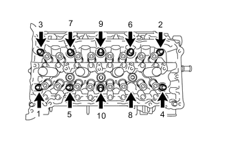
Using a 10 mm bi-hexagon wrench, uniformly loosen the 10 cylinder head bolts in the order shown in the illustration. Remove the 10 cylinder head bolts and 10 plate washers.
Tech Tips
Arrange the removed parts in such a way that they can be reinstalled to their original locations.
-
Remove the cylinder head sub-assembly.
Note
-
Be careful not to drop the plate washers into the cylinder head sub-assembly.
-
Warpage or cracking of the cylinder head sub-assembly may result from removing the cylinder head bolts in the incorrect order.
-
-
-
REMOVE CYLINDER HEAD GASKET
-
Remove the cylinder head gasket from the cylinder block sub-assembly.
-