ПРИВОДНОЙ РЕМЕНЬ ГАЗОРАСПРЕДЕЛЕНИЯ УСТАНОВКА

-
INSPECT TIMING BELT
Note
-
Do not bend, twist or turn the timing belt inside out.
-
Do not allow the timing belt to come into contact with oil, water or steam.
-
Do not utilize timing belt tension when installing or removing the mount bolt of the camshaft timing pulley.
If there are any defects as shown in the illustrations, check the following points:
-
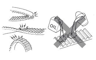
If there is premature parting:
-
Check for proper installation.
-
Check the timing cover gasket for damage and proper installation.
-
-
If the belt teeth are cracked or damaged, check if either camshaft is locked.
-
If there is noticeable wear or cracks on the belt face, check if there are nicks on the side of the idler pulley lock and water pump.
-
If there is wear or damage to only one side of the belt, check the belt guide and the alignment of each pulley.
-
If there is noticeable wear on the belt teeth:
-
Check the timing cover for damage.
-
Check that the gasket has been installed correctly.
-
Check for foreign matter on the pulley teeth.
If necessary, replace the timing belt.
-
-
-
INSPECT TIMING BELT IDLER SUB-ASSEMBLY NO.1
-
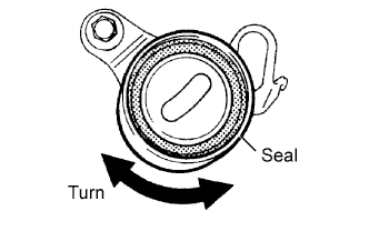
Visually check the seal portion of the timing belt idler No.1 for oil leakage.
If leakage is found, replace the timing belt idler No.1.
-
Check that the timing belt idler No.1 turns smoothly.
If necessary, replace the timing belt idler No.1.
-
-
INSPECT IDLER TENSION SPRING
-
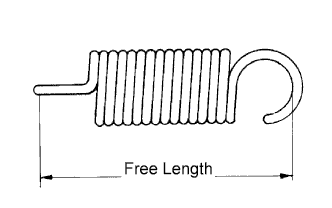
Measure the free length of the tension spring.
Free length 44.4 to 45.4 mm (1.748 to 1.787 in.) If the free length is not as specified, replace the tension spring.
-
Measure the tension of the tension spring at the specified installed length.
Installed tension 53 to 59 N (5.42 to 5.98 kgf, 11.9 to 13.2 lbf) at 52.1 mm (2.051 in.)
-
-
INSPECT ENGINE WATER PUMP ASSEMBLY
-
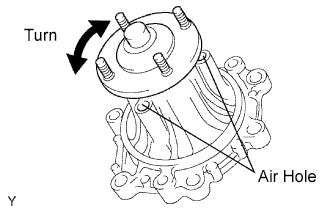
Check that there are no engine coolant leaks from the drain hole.
-
Check that the pulley can be turned smoothly and that there is no abnormal noise from the bearing.
-
-
SET NO.1 CYLINDER TO TDC/ COMPRESSION
-
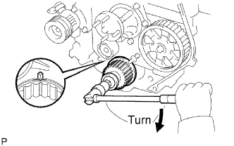
Using the crankshaft pulley bolt, align its groove with the timing pointer by turning the crankshaft clockwise.
Note
Do not turn the crankshaft pulley counterclockwise.
-
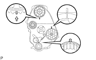
Set the timing and drive pulleys at each position.
Note
-
The engine should be cold.
-
When turning the crankshaft or camshaft, the valve heads will hit against the piston top. Do not turn them more than necessary.
-
-
-
INSTALL TIMING BELT
Tech Tips
If reusing the timing belt, align the points marked during removal, and install the timing belt with the arrow pointing in the direction of engine revolution.
-
Remove any oil or water on each pulleys, and keep them clean.
-
Install the timing belt on the crankshaft timing pulley and timing belt idlers.
-
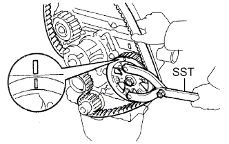
Using SST, slightly turn the injection pump drive pulley clockwise. Hang the timing belt on the pulley, and align the timing marks of the drive pulley and timing belt case.
- SST
- 09960-10010 ( 09962-01000, 09963-01000 )
-
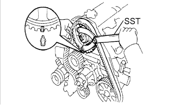
Using SST, slightly turn the camshaft timing pulley clockwise. Hang the timing belt on the timing pulley, and align the timing marks of the timing pulley and timing belt case.
- SST
- 09960-10010 ( 09962-01000, 09963-01000 )
-
Check that the timing belt has tension between the injection pump drive and camshaft timing pulleys.
-
Install the timing belt on the timing belt idler No.2.
-
-
CHECK VALVE TIMING
-
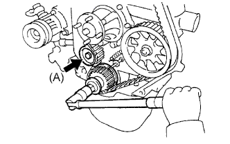
Loosen the timing belt idler No.1 bolt (A), and stretch the timing belt.
-
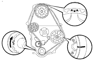
Slowly turn the crankshaft pulley 2 revolutions from TDC to TDC.
Note
Always turn the crankshaft clockwise.
-
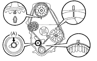
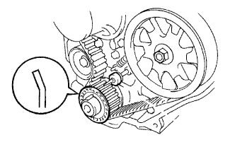
Check each pulley aligns with the timing marks as shown in the illustration.
If the timing marks do not align, remove the timing belt and reinstall it.
-
Tighten the timing belt idler No.1 bolt (A).
- Torque:
- 44 N*m { 450 kgf*cm, 33 ft.*lbf }
-
-
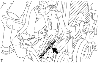
INSTALL TIMING BELT GUIDE
-
Install the belt guide with the cup side facing outward.
-
-
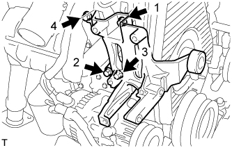
INSTALL TIMING CHAIN OR BELT COVER SUB-ASSEMBLY
-
Remove the 2 nuts and wire harness clamp bracket.
-
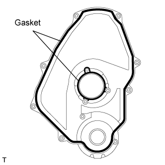
Install the 2 gaskets to the timing belt cover.
-
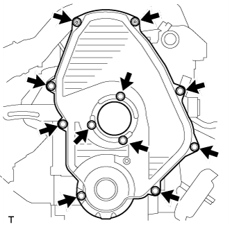
Install the timing belt cover with the 11 bolts.
- Torque:
- 11 N*m { 105 kgf*cm, 8 ft.*lbf }
-
Install the 2 nuts and wire harness clamp bracket.
-
-
INSTALL CRANKSHAFT PULLEY
-
Align the pulley set key with the key groove of the pulley, and slide the pulley to the crankshaft.
-
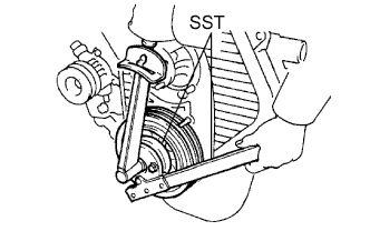
Using SST, install the new pulley bolt.
- SST
- 09213-54015 ( 91651-60855 )
- 09330-00021
- Torque:
- 235 N*m { 2,400 kgf*cm, 173 ft.*lbf }
-
-
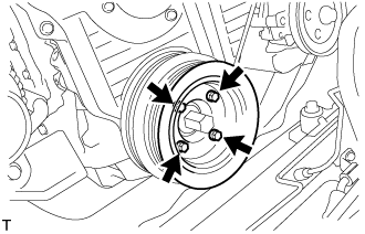
INSTALL VANE PUMP DRIVE PULLEY
-
w/o Air conditioning:
-
Install the vane pump drive pulley and vane pump pulley spacer with the 4 bolts.
- Torque:
- 19 N*m { 195 kgf*cm, 14 ft.*lbf }
-
-
w/ Air conditioning:
-
Install the 2 vane pump drive pulleys with the 4 bolts.
- Torque:
- 18 N*m { 184 kgf*cm, 13 ft.*lbf }
-
-
-
INSTALL COMPRESSOR MOUNTING BRACKET (w/ Air Conditioning)
-
Временно установите кронштейн компрессора и закрепите его 4 болтами.
-
В несколько этапов установите и равномерно затяните 4 болта. Последовательность затяжки показана на рисунке.
- Torque:
- 85 Н*м { 870 кгс*см, 63 фунт-сила-фута }
-
Установите распорную втулку и временно затяните болт.
-
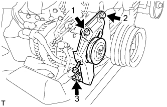
Временно установите кронштейн компрессора и закрепите его 3 болтами.
-
В несколько этапов установите и равномерно затяните 3 болта. Последовательность затяжки показана на рисунке.
- Torque:
- 47 Н*м { 475 кгс*см, 36 фунт-сила-футов }
-
-
INSTALL COMPRESSOR AND MAGNETIC CLUTCH (w/ Air Conditioning)
-
TEMPORARILY TIGHTEN FAN PULLEY
-
Temporarily tighten the fan pulley with the 4 bolts.
-
-
INSTALL FAN & GENERATOR V BELT (w/o Air Conditioning)
-
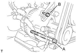
Установите поликлиновой ремень.
-
Отрегулируйте натяжение поликлинового ремня с помощью стержня.
-
Затяните болты А и В.
- Torque:
- Болт A
- 75 Н*м { 765 кгс*см, 55 фунт-сила-фута }
- Болт B
- 18 Н*м { 185 кгс*см, 13 фунт-сила-футов }
-
Проверьте натяжение поликлинового ремня. (см. стр. Click here)
-
-
INSTALL FAN & GENERATOR V BELT (w/ Air Conditioning)
-
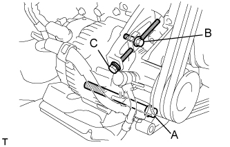
Установите поликлиновой ремень.
-
Отрегулируйте натяжение поликлинового ремня с помощью болта C.
-
Затяните болты А и В.
- Torque:
- Болт A
- 75 Н*м { 765 кгс*см, 55 фунт-сила-футов }
- Болт B
- 18 Н*м { 185 кгс*см, 13 фунт-сила-футов }
-
Проверьте натяжение поликлинового ремня. (см. стр. Click here)
-
-
TIGHTEN FAN PULLEY
-
Install the 4 nuts, fan spacer and fan pulley.
- Torque:
- 19 N*m { 185 kgf*cm, 14 ft.*lbf }
-
-
INSTALL V (COOLER COMPRESSOR TO CRANKSHAFT PULLEY) BELT NO.1 (w/ Air Conditioning)
-
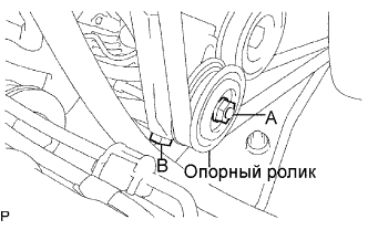
Установите поликлиновой ремень.
-
Затягивая болт В, отрегулируйте натяжение поликлинового ремня.
-
Затяните гайку А.
- Torque:
- 39 Н*м { 400 кгс*см, 29 фунт-сила-футов }
-
Проверьте натяжение поликлинового ремня. (см. стр. Click here)
-
-
INSTALL VANE PUMP V BELT
-
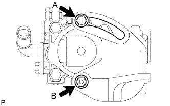
Установите поликлиновой ремень.
-
Отрегулируйте натяжение поликлинового ремня с помощью стержня.
-
Затяните болт А и гайку В.
- Torque:
- Болт (A)
- 48 Н*м { 489 кгс*см, 35 фунт-сила-футов }
- Гайка (B)
- 64 Н*м { 635 кгс*см, 47 фунт-сила-дюймов }
-
Проверьте натяжение поликлинового ремня. (см. стр. Click here)
-
-
INSTALL ENGINE SERVICE HOLE SUB COVER SUB-ASSEMBLY
-
Установите крышку технологического отверстия двигателя и закрепите ее 5 болтами.
- Torque:
- 13 Н*м { 133 кгс*см, 10 фунт-сила-футов }
-
-
INSTALL FRONT DOOR SCUFF PLATE RH
-
INSTALL FRONT SEAT ASSEMBLY RH (for Hi-back Seat Type)
Tech Tips
Use the same procedures described for the LH side. Click here
-
INSTALL FRONT SEAT ASSEMBLY RH (for Low-back Seat Type)
Tech Tips
Use the same procedures described for the LH side. Click here
-
CONNECT CABLE TO NEGATIVE BATTERY TERMINAL
-
ADD ENGINE COOLANT
-
Залейте охлаждающую жидкость в расширительный бачок радиатора до верха горловины.
Номинальный объем Параметр / Устройство Заданные условия Для моделей без подогревателя 12,3 литра (13,0 кварты США, 10,8 английской кварты) Для моделей с передним подогревателем 13,3 литра (14,1 кварты США, 11,7 английской кварты) Для моделей с передним и задним подогревателями 15,3 литра (16,2 кварты США, 13,5 английской кварты) Note
Не доливайте простую воду вместо охлаждающей жидкости двигателя.
Tech Tips
-
Использование неподходящей охлаждающей жидкости может привести к повреждению системы охлаждения двигателя.
-
Разрешается использовать только охлаждающую жидкость "TOYOTA Super Long Life Coolant" или аналогичную высококачественную охлаждающую жидкость на основе этиленгликоля (а не на силикатной, аминовой, нитритной или борнокислой основе), изготовленную по гибридной технологии органических кислот с длительным сроком годности (охлаждающая жидкость, изготовленная по гибридной технологии органических кислот, состоит из низкофосфатных соединений и органических кислот).
-
-

Долейте охлаждающую жидкость в расширительный бачок радиатора до отметки B и установите пробку расширительного бачка радиатора.
-
Прогревайте двигатель, пока не откроется термостат.
-
Когда термостат откроется, несколько минут прокачивайте охлаждающую жидкость.
Tech Tips
Время открывания термостата можно проверить, сжав входной патрубок радиатора рукой и убедившись, что охлаждающая жидкость поступает в шланг.
-
-
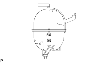
После охлаждения двигателя убедитесь, что уровень охлаждающей жидкости находится между отметками "LOW" и "FULL".
-
-
CHECK FOR ENGINE COOLANT LEAKS
CAUTION:
Не снимайте пробку радиатора, пока двигатель и радиатор не остынут. Выброс горячей охлаждающей жидкости и пара под давлением может стать причиной серьезных ожогов.
-
Заполните радиатор охлаждающей жидкостью и подсоедините к радиатору приспособление для опрессовки системы охлаждения и проверки пробки радиатора.
-
Прогрейте двигатель.
-
С помощью приспособления для опрессовки системы охлаждения и проверки пробки радиатора увеличьте давление в радиаторе до 118 кПа (1,2 кгс/см2, 17,1 фунтов на кв. дюйм) и убедитесь, что давление не падает.
Tech Tips
Если давление снижается, проверьте на наличие утечек шланги, радиатор и насос системы охлаждения. При отсутствии внешних утечек проверьте сердцевину отопителя, блок цилиндров и головку блока цилиндров.
-
-
CHECK IDLE SPEED
-
Warm up the engine.
-
When using an intelligent tester:
-
Connect the intelligent tester to the DLC3.
Idle speed 720 to 820 rpm (A/C OFF) 750 to 850 rpm (A/C ON) Tech Tips
Refer to the intelligent tester operator's manual for further details.
-
-
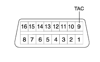
When not using an intelligent tester:
-
Using SST, connect the tachometer test probe to terminal 9 (TAC) of the DLC3.
- SST
- 09843-18040
-
Check the idle speed.
Idle speed 720 to 820 rpm (A/C OFF) 750 to 850 rpm (A/C ON) Note
Switch off all accessories.
-
-
-
INSPECT MAXIMUM ENGINE SPEED
-
Start the engine.
-
Depress the accelerator pedal all the way.
-
Check the maximum speed.
Maximum speed 4,850 to 4,950 rpm
-
-
PERFORM INITIALIZATION